


2
The Hozelock Cyprio Cascade 4000 pump is
designed for submersible use only. The pump
does not use oil or grease for lubrication and
can be used safely in ponds containing fish or
plants. The motor consists of a sealed stator
and water-cooled permanent magnet rotor.
All electrical components are isolated from
the water.
IMPORTANT
1.
WARNING:
ALWAYS UNPLUG OR
DISCONNECT ALL APPLIANCES IN THE
POND FROM THE ELECTRICITY SUPPLY
BEFORE PUTTING YOUR HANDS IN THE
WATER WHILST EQUIPMENT IS BEING
INSTALLED, REPAIRED, MAINTAINED OR
HANDLED.
2. Do not use the supply cable to lift the
pump, as this may cause damage. We
recommend fitting a lifting cord to the
handle eye on the top of the strainer cage
when the pump is installed in deep water.
3. Do not operate or leave the pump in
freezing conditions.
4. Do not allow the pump to run dry.
5. Check that the voltage marked on the
pump corresponds to the mains supply.
6. A 10MA OR 30MA RESIDUAL CURRENT
DEVICE MUST BE FITTED TO THE MAINS
SUPPLY.
7. DO NOT OPERATE THIS PUMP
WITHOUT THE STRAINER CAGE
ATTACHED. USING THE PUMP WITHOUT A
STRAINER CAGE MAY INVALIDATE YOUR
WARRANTY.
Safety Information
The appliance is not intended for use by
persons (including children) with reduced
physical, sensory or mental capabilities,
or lack of experience and knowledge,
unless they have been given supervision
or instruction concerning use of the
appliance by a person responsible for
their safety. Children should be
supervised to ensure that they do not
play with the appliance.
WARNING: SAFETY AND
ELECTRICAL CONNECTIONS
1. The pump is supplied with 10m of 3 core
electric cable which is permanently
connected and sealed to the motor.
The supply cable cannot be replaced. If the
cable is damaged, the pump should be
discarded.
WARNING:
THE PLUG SUPPLIED WITH THIS
PRODUCT IS NOT WATERPROOF AND THE
CONNECTION TO THE MAINS SUPPLY
SHOULD ONLY BE MADE IN A
WEATHERPROOF ENCLOSURE.
The installation must conform to the
national and local wiring regulations
which could include the use of plastic or
metal conduit to protect the cable.
2. A 10MA OR 30MA RESIDUAL CURRENT
DEVICE (RCD) MUST BE FITTED TO THE
MAINS SUPPLY.
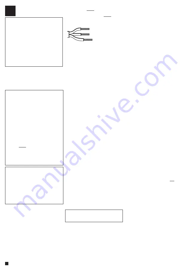
3. WARNING: THIS APPLIANCE MUST BE
EARTHED AND IT IS ESSENTIAL THAT THE
CONNECTIONS ARE MADE USING THE
FOLLOWING CODE;
Brown - Live
Blue - Neutral
Green/Yellow - Earth
The BROWN lead should be connected to
the LIVE terminal which may be marked
with an ‘L’ or coloured brown or red.
The BLUE lead should be connected to the
NEUTRAL terminal which may be marked
with an ‘N’ or coloured blue or black.
The GREEN/YELLOW lead should be
connected to the EARTH terminal which
may be marked with an ‘E’ or coloured
green or green/yellow.
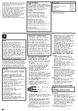
4. If an extension cable is required, this
should be connected to the end of the
pump cable using a weatherproof cable
connector. The joint must be positioned in
a suitable weatherproof housing. The
extension cable should be of 3 core
0.75mm
2
Polychloroprene rubber insulated
cable (ref: HO5 RN-F) and permanently
wired to the mains supply with a 3 or 5
Amp fuse.
5. The pump cable (and extension cable)
should be positioned and adequately
protected against damage especially
where contact with gardening equipment
(lawn mowers, forks etc.) children and
domestic animals may occur.
6. CONSULT A QUALIFIED ELECTRICIAN OR
LOCAL AUTHORITY IF IN ANY DOUBT
ABOUT WIRING TO THE MAINS SUPPLY.
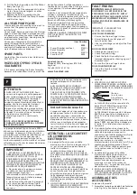
ACCESSORY ASSEMBLY
Tee Piece
1. Locate the fountain flow adjuster (See
Fig1-A) to the tee piece body with the peg
positioned downwards to engage in the
tee. Push in fully and snap them together.
2. Locate the valve stem (B) to the waterfall
flow adjuster (C) and snap them together.
Screw the valve assembly into the longer
boss (D) on the tee piece. See fig 1.
Telescopic Stem
1. Slide the Inner Tube (E) through the
Telescopic Stem Nut (F) and “O” ring (G).
Push the Inner Tube into the Outer Tube
(H) and gently screw down the nut. The
finishing position of the tee piece is not
important. The maximum to minimum
range of the Telescopic stem is 150mm (6”)
(See fig 2).
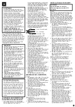
Bell Fountain
1. Locate the Bell Support (I) to the Bell Main
Body (J) and push fully home.
2. Position the Bell (K) to the Body Assembly
and press into the central location.
See fig 3.
PUMP INSTALLATION
ATTENTION: This product is not
suitable for water temperatures
above 35ºC
Position
Construct a solid and level platform on which
to place the pump. For installations using the
fountain tops directly on the Tee Piece, the
top level of the platform should be 300 mm
(12”) below the water level. For installations
using the fountain tops directly on the Tee
Piece and Telescopic Stem , the top level of
the platform should be 450 mm (18”) below
the water level.
Fountain Only.
(See Fig 7 for general
installation guide)
1. Place the pump next to the pond and
route the cable back to the mains supply.
2. Position the pump with the Tee Piece
Assembly and if required the Telescopic
Stem with the fountain fitted in the
desired position in the pond. The 2 and 3
tier fountain heads simply snap onto the
fountain stem (See Fig 4).
3. The fountain height can be regulated to
suit your needs by rotating the Fountain
Flow Adjuster. See Fig 5 (L).
4. If required, the 2-Tier Fountain head, Fig 5
(M), can be used to achieve an alternative
and higher display pattern than the 3-Tier,
Fig 5 (N).
5. The Bell Fountain creates a decorative
waterbell. The size of the bell can be
regulated by adjusting the flow through
the Tee Piece by rotating the fountain
flow adjuster and or by raising or lowering
the top of the Bell in main Bell Body.
6. The ball joint on the bottom of the tee
Piece (See Fig 5, O) can be used to adjust
the fountain angle so that it is vertical.
Fountain and Waterfall.
(See Fig 8 for general
installation guide)
1. Position the pump as previously described.
2. Attach a suitable length of 25 mm (1”)
hose to the Threaded Hose tail, Fig 5 (P),
and secure with a suitable hose clip and
position the outlet end of the hose in the
desired position.
3. Screw the Threaded Hose tail onto the
waterfall outlet side of the Tee Piece.
4. The combination of waterfall and
fountain will reduce the fountain height
that can be achieved.
5. Once the pump is operating the flow of
the waterfall and the height of the
fountain can be independently adjusted.
Waterfall Only.
(See Fig 9 for general
installation guide)
1. Position the pump as previously described.
2. Attach a suitable length of 25 mm (1”)
hose to the Threaded Hose tail and secure
with a suitable hose clip and position the
outlet end of the hose in the desired
position.
3. For maximum waterfall flow, screw the
Threaded Hose tail directly onto the outlet
of the pump. Some installations require
the flow of the water to be adjusted. In
these cases, screw the Tee Piece to the
outlet of the pump, screw the Threaded
Hose tail to the water fall outlet boss and
adjust the flow using the waterfall flow
adjuster, Fig 5 (Q), to suit your needs.
MAINTENANCE
The Hozelock Cyprio range of Cascade pumps
has been designed to allow fast and easy
maintenance. As with all pumps of its kind,
occasionally it will become necessary to clean
the Strainer Cage and Fountain Spray head
ring.
ALWAYS UNPLUG OR DISCONNECT ALL
APPLIANCES IN THE POND FROM THE
ELECTRICITY SUPPLY BEFORE PUTTING YOUR
HANDS IN THE WATER OR STARTING
MAINTENANCE.
Fountain Head
1. Place a coin or similar in the slot and
gently lever off the fountain head.
2. Rinse in clean water and reassemble.
Strainer
1. Remove the accessories from the pump
outlet.
2. Holding the pump in one hand, press the
release button on the top of the pump
and open Strainer Cage. See Fig 5 (R).
3. Slide the pump out of its location and
wash/rinse the Strainer Cage with clean
water. The hinges on the Strainer Cage
should also be washed clean at this time.
4. Reassemble the pump.
Rotor Assembly
1. Remove the Strainer Cage as described
above.
2. Release the Pump Chamber, Fig 6 (S), by
rotating it until the two retaining tongues
are clear of the lugs on the Motor Body.
3. Gently pull the Pump Chamber squarely
away from the Motor Body.
GB
ATTENTION
AUTOMATIC CUT-OUT
. To help ensure
your pump’s long life and to prevent
damage, it is fitted with automatic
thermal overload protection. This
switches off the pump if it overheats. If
this occurs, switch off the power at the
mains supply to the pump. Check for the
cause. Usually it will be debris blocking
the inlets of the pump or obstructing the
impeller. Remove the obstruction and
wait 15 minutes for the pump to cool
down and automatically reset. Then
switch on the pump again.
NOTE: YOU MUST SWITCH OFF THE MAINS
SUPPLY BEFORE THE PUMP WILL RESET.


