

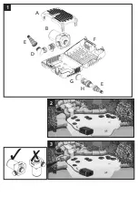


ASSEMBLY
1. Open the clips at either end of the strainer cage (Fig 1 –
f) and open the cage.
2. Remove the Wildlife Protection system (Fig1 – a).
3. Remove & unpack the ball joint, hosetails & Flow control
(Fig 1 – d, e & h).
4. Remove the mains supply cable and unwind.
5. Ensure that the outlet of the pump is secured to the
outlet adaptor (Fig 1 – c). Locate the pump onto its
mounting area ensuring that the adaptor piece slots into
the location ribs in the front of the lower cage (Fig 4).
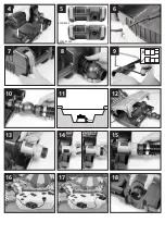
Note:
For the 6000 & 8000 pump the adaptor should be
orientated with the outlet at the bottom of the cage (fig
5). For the 12000 & 15000 pumps, the adaptor should be
orientated with the outlet towards the top of the cage (Fig
5).
6. Locate the mains supply cable into the recess on the side
of the cage. Ensure it is seated in the correct position so
that the cable does not get trapped when the cage is
closed. (Fig 6).
7. Close the cage lid ensuring that the end cap (Fig 1 – g) is
in its correct position and secure by pressing in the centre
of the clips (Fig 7).
8. Checking that the ball joint’s inlet and outlet bosses are
in line, firmly screw the nut on to the screw thread on the
outlet adaptor (Fig 8).
9. Using small bore hoses leads to excessive restriction of
the water flow. The larger the diameter of hose that you
use the better the performance of the pump will be,
especially over long hose runs. The hosetail supplied with
this unit will accommodate 25mm (1"), 32mm (1.25") and
40mm (1.6") hose as well a ¾” BSP screw thread for
attaching fountain accessories.
We would always
recommend that on pumps of this size, that the 40mm
diameter hose should be used when using the pump as a
waterfall pump or in combination with a filter (Fig 2 & 3)
.
Once you have selected the hose diameter you wish to use,
cut the steps off the hosetail which are smaller than the
hose diameter to eliminate restriction (Fig 9). Attach a
suitable length hose to the hosetail and secure with a
suitable hose clip and position the outlet end of the hose
in the desired position.
10. Screw the hosetail directly onto the outlet boss of the
ball joint (Fig 10). The ball joint can be rotated to allow the
hose to be directed away from the pump.
POSITION
11. For the best results, the pump should be positioned in
the deepest part of the pond at least 200mm under the
surface. This will ensure the best circulation of water in the
pond and when being used as a filtration pump, its solids
handling capability will be maximised.
For best results, the pump should not be placed directly on
the bottom of the pond. We recommend that the pump be
installed on a flat level platform which is raised
approximately 300mm from bottom of pond. This will
prevent the pump sucking dirt directly from the bottom of
the pond and will also ensure that sufficient water remains
in the pond in the event of accidental leakage of pond
water (See fig 11).
Wildlife Protection System (WPS)
12. If you have fish or other wildlife in your pond, there
are periods in the year during which they may breed. At
this time the fish ‘fry’ are small and can be sucked into the
pump. To minimise this possibility, the Aquaforce range of
pumps has a unique Wildlife Protection System (WPS),
which reduces the inlet strainer hole size down to 2mm at
this critical time in fishes’ life cycle. To use this feature,
locate the WPS’s 4 legs into the corresponding area in the
lower cage as shown in Fig 12 ensuring that the WPS is the
correct way round. Close the top of the cage and secure
the clips. Whilst the WPS is in use, you may need to
unblock the strainer cage more frequently. Once the fish or
other wildlife have grown to a sufficient size you can then
remove the WPS from your pump’s cage and return the
strainer size to its maximum 10mm size.
The flow Control (Fig 1 - h) can vary the amount of water
entering the pump. Alternatively, it can be used to connect
a second inlet to the pump such as a satellite filter or a
skimmer. Do not use the flow control when the pump is
being used amphibiously.
1. Open the cage and remove the end cap (Fig 1 - g).
2. Close the flow control by rotating the outer part until
the arrows are aligned.
3. Firmly screw the flow control to the inlet of the pump
aligning the arrows on the flow control with the arrow in
the centre of the top of the pump chamber (Fig 13).
4. Locate the pump into the cage. Ensure that the slots in
the outlet adaptor align with the ribs in the lower cage
and that the grip of the flow control is on the outside of
the cage (Fig 4).
5. To use as a flow control, screw the end cap to the free
end of the flow control.
6. Rotate the grip to the desired position. This varies the
opening size on the flow control. The arrow on the grip
aligns with the pointer on the outside of the top cage.
When the pointed end of the arrow is aligned with the
pointer on the outside of the filter cage, this indicates
minimum flow. When the wide end of the arrow is aligned
with the pointer, this indicates maximum flow (See fig 14).
7. Locate the cable into its recess (See point 6 under
Submerged Operation), close the cage lid and secure the
clips.
8. To use a second inlet connect a suitable length of hose
to a hosetail which has been cut to a suitable diameter and
screw to the free end of the flow control in place of the
end cap (Fig 15).
9. The other end of the hose can be connected to a
satellite filter (Fig 17) (available as a spare from Hozelock)
or to a skimmer (Fig 16).
10. By rotating the grip of the flow control, the amount of
water coming through the satellite filter or skimmer can be
varied.
This pump can be used amphibiously (i.e. it can be used
whilst not submerged).
WARNING!
Ensure that the unit does not take in air or run
dry otherwise your pump will be damaged!
NOTE
: This pump does not self prime. The suction hose and
pump must be filled with water before switching on.
1. Open the clips at either end of the strainer cage, open
the cage, and remove all the contents.
2. Unscrew the outlet adaptor from the pump outlet and
locate it into the ribs in the lower cage (Fig 18)
3. Place the pump under the surface of the water near the
side of the pond to allow water to flow into the pumping
chamber (not self priming) (Fig 19).
4. Cut 2 hosetails to the required size (See point 9 under
Submerged Operation). Attach a suitable length hose to
Pump Assembly & Installation
- Submerged Operation
Using the Flow Control
Pump Installation
- Amphibious
Summary of Contents for Aquaforce 12000
Page 2: ......
Page 3: ...2 3 3 7 A B E D F G H E 1...
Page 4: ...300mm 6 9 12 4 7 10 8 11 5 6000 8000 12000 15000 15 13 14 18 16 17...
Page 5: ...21 19 24 20 23 22 d c b a d c b a...
Page 55: ......


