disposed of according to local regulations.
1.11 A 30mA maximum Residual Current Device
(RCD) MUST be fitted to the mains supply.
1.12 Permanent installations to the mains supply
(hard wiring), must conform to the national and
local wiring regulations. If in any doubt about
wiring to the mains supply, consult a qualified
electrician or local electricity authority.
1.13 Do not use the supply cable to lift the unit, as
this may cause damage. We recommend fitting
a lifting cord to the hook feature on the base,
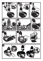
when the filter is installed in deep water. (Fig
1-H). If the product needs to be moved, the
product should be switched off and lifted out of
the water using this cord.
1.14 Do not switch the pump on out of water! The
water level should be above the UVC indicator at
the ball joint (Fig 4A-L).
1.15 Do not operate or leave the unit in freezing
conditions. (See the section, “Winter Storage”).
1.16 This product is not suitable for water
temperatures above 35ºC or below 0ºC.
1.17 Only use accessories which have been designed
for use with this product. The use of any other
accessories or spares may invalidate your
guarantee.
Overload Protection
To help ensure your EasyClear’s long life and to
prevent damage, it is fitted with automatic thermal
overload protection. This switches the pump or UV
lamp off if either overheats. If this occurs, switch off
the power at the mains supply to the unit. If it is the
pump that has activated the Overload Protection,
check for the cause (it is usually debris blocking the
inlet of the pump or obstructing the impeller). Remove
the obstruction and wait 15 minutes for the unit to
cool down. Then switch it on again.
If it is the UV lamp that is activating the overload
protection (pump is still running but UV lamp keeps
going out after running for a short time), please
contact Hozelock Consumer Services Helpline on +44
(0)121 313 1122.
Remember: The lamp is fitted with an interlock that
will turn the lamp off when the bayonet is removed
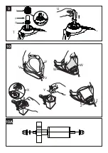
(fig 8-S), so you can only see if the lamp is working in
dark conditions, by looking for a bluish glow from the
Fountain outlet (Fig 1-A) with the bayonet tube locked
in position.
NOTE: YOU MUST SWITCH OFF THE MAINS
SUPPLY BEFORE THE UNIT WILL RESET.
CAUTION: To avoid a safety hazard due to inadvertent
resetting of the thermal overload protection, this
product must not be used with an external switching
device, such as a timer, or connected to a circuit that is
regularly switched on and off by the electricity supply.
Periods of Operation
Keep the filter working 24 hours a day. Ideally it
should run all year round, but at least throughout the
fish-feeding season, (i.e. until the water temperature
falls below 10°C and the fish stop feeding). In winter,
operating the unit will maintain a basic level of useful
bacteria in the Biological Filter, and will help prevent
the pond icing over. However, the unit must not be
allowed to freeze. If you switch the unit off for winter,
wash the unit thoroughly before resuming filtration in
the spring (see ‘Winter Storage’). Never feed your fish
when the unit is not in use.
Before First Use
Inappropriate handling of this product during transit
may result in damage to the quartz tube. Please
inspect the quartz tube and seal before installation.
See the section “Maintenance” for details on how to
access the quartz tube and lamp.
Installation
Position - Construct a solid and level platform on
which to place the EasyClear™. The platform should be
greater than 300 mm (12”) below the water level. For
depths between 300mm and 600mm use the fountain
stem extension segments (Fig 1-F), which simply screw
together, to allow the fountain to be above the water
level. For general installation see Fig 4-A/B. When
using the EasyClear for a waterfall the entire unit
should be submersed.
Connection - Place the unit next to the pond and
route the cable back to the mains supply. Ensure that
you allow for enough cable for positioning the product
in the desired location in the pond.
Accessory Assembly
Bell Fountain (Fig 1).
Locate the Bell Support (B) to the Bell Main Body (C)
and push fully home.
Position the Bell (D) to the Body Assembly and press
into the central location.
2 and 3 tier fountain display assembly (Fig 1-I).
The plastic discs (Fig 1-E) that create the 2 and 3
tier water displays simply snap onto the fountain
stem. Push the fountain stem into the fountain stem
extension segment and screw onto the fountain outlet
(Fig 1-A).
Fountain Only Operation
(Fig 4-A for general installation guide)
Please note: The product has a water by-pass to
control water flow rates which means a quantity
of water will always come out of the product just
Summary of Contents for EasyClear 3000 1760
Page 2: ...1 4A 3 5 6 7 4B 8 2 P P O N L Q J K G C E D B A I F H R S M...
Page 3: ...V X Y V V Z Z W W 10 9 10A T i ii iii U...
Page 69: ......
Page 70: ......
Page 71: ......


