


coloured blue or black. The
GREEN/YELLOW lead should be
connected to the EARTH terminal
which may be marked with an 'E' or
coloured green or green/yellow.
• If an extension cable is required, this
should be connected to the end of the
unit cable using a weatherproof
connector. The joint must be positioned
in a suitable weatherproof housing.
The extension cable should be of 3 core
0.75mm2 Polychloroprene rubber
insulated cable (ref: HO5 RN-F) and
permanently wired to the mains supply
with a 3 or 5 Amp fuse.
• The unit cable (and extension cable)
should be positioned and adequately
protected against damage especially
where contact with gardening
equipment (lawn mowers, forks etc.)
children and domestic animals may
occur.
• CONSULT A QUALIFIED ELECTRICIAN
OR LOCAL AUTHORITY IF IN ANY
DOUBT ABOUT WIRING TO THE MAINS
SUPPLY.
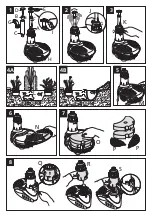
Position -
Construct a solid and level
platform on which to place the
EasyClear™. The platform should be
greater than 300 mm (12") below the
water level. For depths between
300mm and 600mm use the fountain
stem extension segments (Fig 1-F),
which simply screw together, to allow
the fountain to be above the water
level. For general installation see Fig 4
A/B. When using the EasyClear for a
waterfall the entire unit should be
submersed.
Connection -
Place the unit next to the
pond and route the cable back to the
mains supply. Ensure that you allow for
enough cable for positioning the
product in the desired location in the
pond.
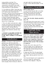
Bell Fountain (Fig 1).
Locate the Bell Support (B) to the Bell
Main Body (C) and push fully home.
Position the Bell (D) to the Body
Assembly and press into the central
location
.
2 and 3 tier fountain display assembly
(Fig 1-E).
The plastic discs that create the 2 and 3
tier water displays simply snap onto the
fountain stem. Push the fountain stem
into the fountain stem extension
segment and screw onto the fountain
outlet (Fig 1-A).
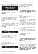
(Fig 4-A for general installation guide)
Please note: The product has a water
by-pass to control water flow rates
which means a quantity of water will
always come out of the product just
below the flow control. This is normal
in operation.
Position the unit in the pond. The
fountain angle can be adjusted to be
vertical using the ball joint (Fig 2-A).
The tightness of the ball joint can be
adjusted (Fig 2-J)
If required, the 2-Tier Fountainhead
can be used to achieve an alternative
and higher display pattern than the 3-
Tier.
The fountain height can be adjusted to
suit your needs by rotating the
Fountain Flow Adjuster. (Fig 3-K)
Fountain Only
Operation
Accessory Assembly
Installation


