5–42
Maintenance and Service Guide
Removal and Replacement Procedures
5.13 Top Cover
1. Prepare the computer for disassembly (
Section 5.3
) and
remove the following components:
❏
Hard drive (
Section 5.4
)
❏
Mini Card compartment cover (
Section 5.8
)
❏
Optical drive (
Section 5.9
)
❏
Keyboard (
Section 5.10
)
❏
Switch cover (
Section 5.11
)
❏
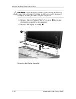
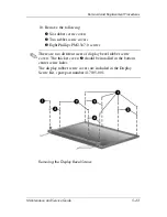
Display assembly (
Section 5.12
)
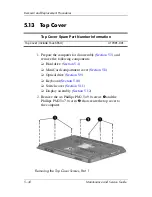
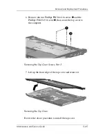
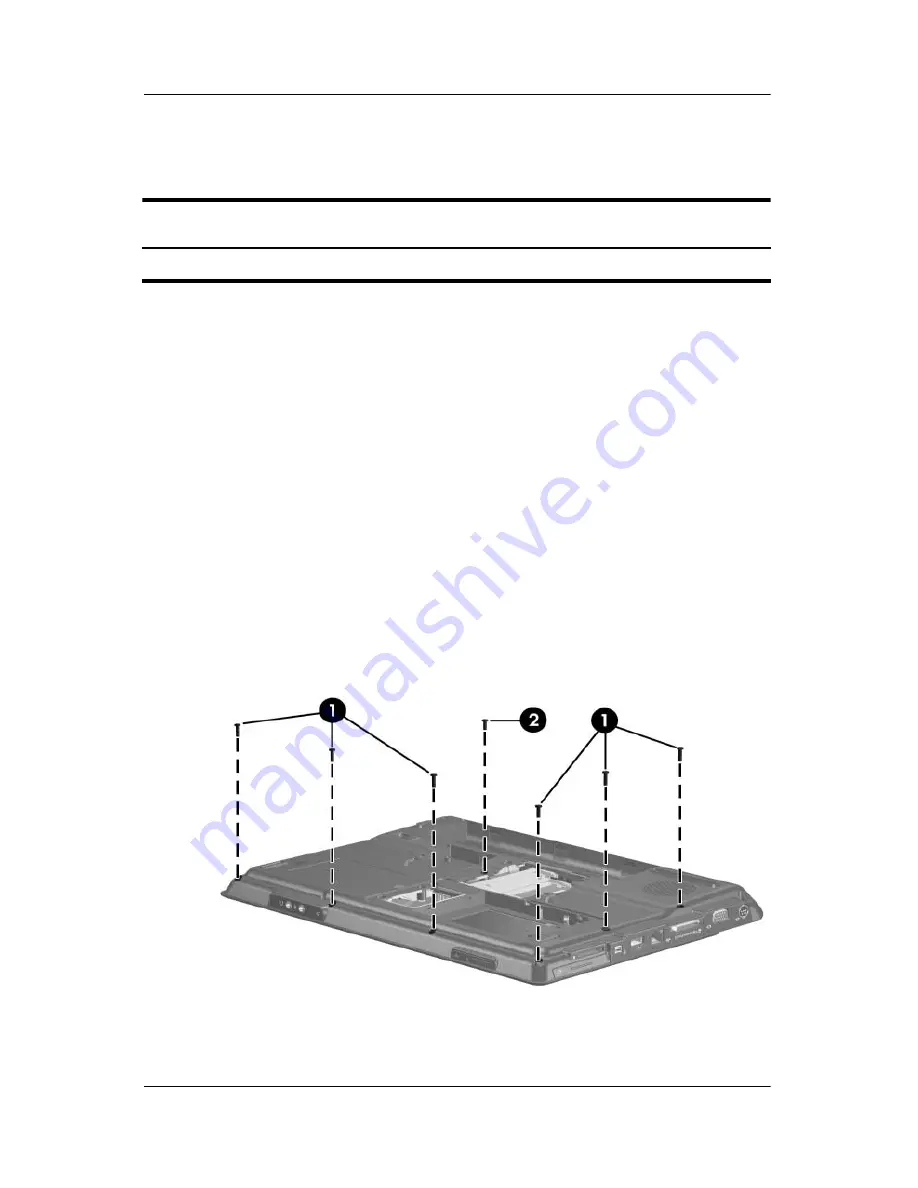
2. Remove the six Phillips PM2.5×9.0 screws
1
and the
Phillips PM2.5×7.0 screw
2
that secure the top cover to
the computer.
Removing the Top Cover Screws, Part 1
Top Cover Spare Part Number Information
Top cover (include TouchPad)
417091-001
Summary of Contents for Compaq Presario,Presario V3000T
Page 68: ...3 4 Maintenance and Service Guide Illustrated Parts Catalog Computer Major Components ...
Page 70: ...3 6 Maintenance and Service Guide Illustrated Parts Catalog Computer Major Components ...
Page 72: ...3 8 Maintenance and Service Guide Illustrated Parts Catalog Computer Major Components ...
Page 74: ...3 10 Maintenance and Service Guide Illustrated Parts Catalog Computer Major Components ...
Page 76: ...3 12 Maintenance and Service Guide Illustrated Parts Catalog Computer Major Components ...
Page 78: ...3 14 Maintenance and Service Guide Illustrated Parts Catalog Computer Major Components ...
Page 80: ...3 16 Maintenance and Service Guide Illustrated Parts Catalog Computer Major Components ...

