background image


88 


8.   

Plug in the computer and turn on power. Allow the operating system to start. This clears the current 

passwords and disables the password features. 

9.   

To establish new passwords, repeat steps 1 through 4, replace the password jumper on pins 1 

and 2, then repeat steps 6 through 8. Establish the new passwords in Computer Setup. 


Clearing and Resetting the CMOS 

The computer’s configuration memory (CMOS) stores information about the computer’s configuration. 

The CMOS jumper resets CMOS but does not clear the supervisor and user passwords. 

1.   

Turn off the computer and any external devices, and disconnect the power cord from the power 

outlet. 

2.   

Disconnect the keyboard, monitor, and any other external equipment connected to the computer. 

WARNING! 

To reduce the risk of personal injury from electrical shock and/or hot surfaces, be 

sure to disconnect the power cord from the wall outlet, and allow the internal system components 

to cool before touching. 

CAUTION: 

When the computer is plugged in, the power supply always has voltage applied to 

the system board even when the unit is turned off. Failure to disconnect the power cord can result 

in damage to the system. 

Static electricity can damage the electronic components of the computer or optional equipment. 

Before beginning these procedures, ensure that you are discharged of static electricity by briefly 

touching a grounded metal object 

3.   

Remove the computer cover or access panel. 

CAUTION: 

Resetting the CMOS jumper will reset CMOS values to factory defaults. It is 

important to back up the computer CMOS settings before resetting them in case they are needed 

later. Back up is easily done through Computer Setup. 

4.   

Locate the header and jumper. 

NOTE: 

For assistance locating the CMOS jumper and other system board components, see the 

Illustrated Parts & Service Map (IPSM) for that particular system. The IPSM can be downloaded 

from 

http://www.hp.com/support

CAUTION: 

Make sure you have disconnected the AC power cord from the wall outlet. Clearing 

the CMOS while power is connected can damage the system board. 

5.   

Remove the jumper from pins 1 and 2. Place the jumper on pins 2 and 3. 

6.   

Place the jumper back on pins 1 and 2. 

7.   

Replace the computer cover or access panel. 

8.   

Reconnect the external devices. 

9.   

Plug in the computer and turn on power. 

NOTE: 

You will receive POST error messages after clearing CMOS and rebooting advising you 

that configuration changes have occurred. Use Computer Setup to reset any special system setups 

along with the date and time. 


Summary of Contents for 100B SFF

Page 1: ...Maintenance Service Guide 100B SFF PC ...

Page 2: ...ompanying such products and services Nothing herein should be construed as constituting an additional warranty HP shall not be liable for technical or editorial errors or omissions contained herein This document contains proprietary information that is protected by copyright No part of this document may be photocopied reproduced or translated to another language without the prior written consent o...

Page 3: ...ions could result in bodily harm or loss of life CAUTION Text set off in this manner indicates that failure to follow directions could result in damage to equipment or loss of information NOTE Text set off in this manner provides important supplemental information About This Book ...

Page 4: ...iv ...

Page 5: ... Power 10 Computer Setup Advanced 10 3 Serial ATA SATA Drive Guidelines and Features 12 SATA Hard Drives 12 SATA Hard Drive Cables 12 SATA Data Cable 12 SMART ATA Drives 13 Hard Drive Capacities 13 4 Identifying the Chassis Routine Care and Disassembly Preparation 14 Chassis Designation 14 Small Form Factor 14 Electrostatic Discharge Information 15 Generating Static 15 Preventing Electrostatic Dam...

Page 6: ...y 22 Access Panel 23 Front Bezel 24 Installing Additional Memory 25 DIMMs 25 DDR3 SDRAM DIMMs 25 Populating DIMM Sockets 25 Installing DIMMs 26 Cable Management 28 Cable Connections 28 100B SFF PC 28 Drives 29 Drive Positions 29 Installing and Removing Drives 30 System Board Drive Connections 31 Removing the Optical Drive 31 Removing the Hard Drive 32 Front I O Assembly 34 Power Switch LED Assembl...

Page 7: ... 47 Protecting the Software 48 8 Troubleshooting Without Diagnostics 49 Safety and Comfort 49 Before You Call for Technical Support 49 Helpful Hints 50 Solving General Problems 52 Solving Diskette Problems 56 Solving Hard Drive Problems 58 Solving Media Card Reader Problems 59 Solving Display Problems 61 Solving Audio Problems 64 Solving Printer Problems 66 Solving Keyboard and Mouse Problems 67 S...

Page 8: ...e CMOS 88 Appendix A Connector Pin Assignments 89 Ethernet BNC 89 USB 89 Microphone 89 Headphone 90 Line in Audio 90 Line out Audio 90 4 Pin Power for CPU 90 Monitor 91 24 Pin Power 91 PCI Express 92 PCI Express 93 Appendix B Power Cord Set Requirements 94 General Requirements 94 Japanese Power Cord Requirements 94 Country Specific Requirements 95 Appendix C Specifications 96 100B SFF PC models 96...

Page 9: ... 2 cm 4 inch clearance at the back of the unit and above the monitor to permit the required airflow Installing the Operating System The first time you turn on the computer the operating system is installed automatically This process takes about 5 to 10 minutes depending on which operating system is being installed Carefully read and follow the instructions on the screen to complete the installatio...

Page 10: ...ton in the dialog box to locate the i386 folder This action points the operating system to the appropriate drivers Obtain the latest support software including support software for the operating system from http www hp com support Select your country and language select Download drivers and software and firmware enter the model number of the computer and press Enter Accessing Disk Image ISO Files ...

Page 11: ...lected To manually switch to Post Messages Enabled during POST press any key except F1 through F12 Enter the Asset Tag or property identification number assigned by the company to this computer Enable the power on password prompt during system restarts warm boots as well as during power on Establish a setup password that controls access to the Computer Setup F10 Utility and the settings described ...

Page 12: ...age Security Power and Advanced 5 Use the arrow left and right keys to select the appropriate heading Use the arrow up and down keys to select the option you want then press Enter To return to the Computer Setup Utilities menu press Esc 6 To apply and save changes select File Save Changes and Exit If you have made changes that you do not want applied select Ignore Changes and Exit To reset to fact...

Page 13: ...ize speed number of channels single or dual if applicable Integrated MAC address for embedded enabled NIC if applicable System BIOS includes family name and version Chassis serial number About Displays copyright notice Set Time and Date Allows you to set system time and date Apply Defaults and Applies the currently selected default settings and clears any established passwords Exit Ignore Changes ...

Page 14: ...UNIX version 3 2 Options are Automatic Bit Shift LBA Assisted User and Off Available only when the drive translation mode is set to User allows you to specify the parameters logical cylinders heads and sectors per track used by the BIOS to translate disk I O requests from the operating system or an application into terms the hard drive can accept Logical cylinders may not exceed 1024 The number of...

Page 15: ...n at least one drive capable of performing the DPS selftests is attached to the system Allows you to Specify the order in which EFI boot sources such as a internal hard drive USB hard drive USB optical drive or internal optical drive are checked for a bootable operating system image Each device on the list may be individually excluded from or included for consideration as a bootable operating syst...

Page 16: ...et it is required to change Computer Setup options flash the ROM and make changes to certain plug and play settings under Windows NOTE This selection will only appear when at least one drive that supports the DriveLock feature is attached to the system See the Desktop Management Guide for more information Allows you to set and enable a power on password The power on password prompt appears after a...

Page 17: ... Identifier UUID number The UUID can only be updated if the current chassis serial number is invalid These ID numbers are normally set in the factory and are used to uniquely identify the system Keyboard locale setting for System ID entry Data Execution Prevention enable disable Helps prevent operating system security breaches Default is enabled Virtualization Technology VTx some models enable dis...

Page 18: ...e Default is disabled After Power Loss off on previous state Default is Power off Setting this option to Power off causes the computer to remain powered off when power is restored Power on causes the computer to power on automatically as soon as power is restored Previous state causes the computer to power on automatically as soon as power is restored if it was on when power was lost NOTE If you t...

Page 19: ... another video controller is present in the system Default is enabled NIC Option ROM Download PXE iSCSI disabled The BIOS contains an embedded NIC option ROM to allow the unit to boot through the network to a PXE server This is typically used to download a corporate image to a hard drive The NIC option ROM takes up memory space below 1MB commonly referred to as DOS Compatibility Hole DCH space Thi...

Page 20: ...5 V 12 V Jumpers for configuring drive N A Data transfer rate 3 0 Gb s SATA Hard Drive Cables SATA Data Cable Always use an HP approved SATA 3 0 Gb s cable as it is fully backwards compatible with the SATA 1 5 Gb s drives Current HP desktop products ship with SATA 3 0 Gb s hard drives SATA data cables are susceptible to damage if overflexed Never crease a SATA data cable and never bend it tighter ...

Page 21: ...er determines the maximum usable size of a drive partition A drive partition is the largest segment of a drive that may be properly accessed by the operating system A single hard drive may therefore be subdivided into a number of unique drive partitions in order to make use of all of its space Because of the differences in the way that drive sizes are calculated the size reported by the operating ...

Page 22: ...omputer is plugged into an AC power source voltage is always applied to the system board You must disconnect the power cord from the power source before opening the computer to prevent system board or component damage Chassis Designation Small form factor chassis are available Small Form Factor Figure 4 1 Small form factor 4 Identifying the Chassis Routine Care and Disassembly Preparation ...

Page 23: ...across carpet Walking across vinyl floor Motions of bench worker Removing DIPs from plastic tube Removing DIPs from vinyl tray Removing DIPs from Styrofoam Removing bubble pack from PCB Packing PCBs in foam lined box These are then multi packaged inside plastic tubes trays or Styrofoam NOTE 700 volts can degrade a product Preventing Electrostatic Damage to Equipment Many electronic components are ...

Page 24: ... use them on both feet with a maximum of one megohm 10 resistance between the operator and ground Static Shielding Protection Levels Method Voltage Antistatic plastic Carbon loaded plastic Metallized laminate Grounding the Work Area To prevent static damage at the work area use the following precautions Cover the work surface with approved static dissipative material Provide a wrist strap connecte...

Page 25: ...earance on all vented sides of the computer and above the monitor to permit the required airflow Never restrict the airflow into the computer by blocking any vents or air intakes Do not place the keyboard with the keyboard feet down directly against the front of the desktop unit as this also restricts airflow Occasionally clean the air vents on all vented sides of the computer Lint dust and other ...

Page 26: ... alcohol No rinsing is needed as the alcohol will evaporate quickly and not leave a residue After cleaning always wipe the unit with a clean lint free cloth Occasionally clean the air vents on the computer Lint and other foreign matter can block the vents and limit the airflow Cleaning the Keyboard Follow all safety precautions in General Cleaning Safety Precautions on page 18 before cleaning the ...

Page 27: ...er Case on page 18 Cleaning the Mouse Before cleaning the mouse ensure that the power to the computer is turned off Clean the mouse ball by first removing the retaining plate and the ball from the housing Pull out any debris from the ball socket and wipe the ball with a clean dry cloth before reassembly To clean the mouse body follow the procedures in Cleaning the Computer Case on page 18 Service ...

Page 28: ...ced CAUTION When servicing this computer ensure that cables are placed in their proper location during the reassembly process Improper cable placement can damage the computer Hard Drives Handle hard drives as delicate precision components avoiding all physical shock and vibration This applies to failed drives as well as replacement spares If a drive must be mailed place the drive in a bubble pack ...

Page 29: ...hium battery There is a risk of fire and chemical burn if the battery is handled improperly Do not disassemble crush puncture short external contacts dispose in water or fire or expose it to temperatures higher than 140º F 60º C Do not attempt to recharge the battery NOTE Batteries battery packs and accumulators should not be disposed of together with the general household waste In order to forwar...

Page 30: ...disc or media card from the computer 5 Turn off the computer and any peripheral devices that are connected to it CAUTION Turn off the computer before disconnecting any cables Regardless of the power on state voltage is always present on the system board as long as the system is plugged into an active AC outlet In some systems the cooling fan is on even when the computer is in the Standby or Suspen...

Page 31: ...sassembly on page 22 2 If the computer is on a stand remove the computer from the stand 3 Loosen the thumbscrew 1 and then grasp the handle and remove the panel from the computer 2 Figure 5 1 Removing the Access Panel To install the access panel reverse the removal procedure ...

Page 32: ...ssembly Preparation for Disassembly on page 22 2 Remove the access panel Access Panel on page 23 3 Lift up the three tabs on the side of the bezel 1 then rotate the bezel off the chassis 2 Figure 5 2 Removing the Front Bezel To install the front bezel reverse the removal procedure ...

Page 33: ...port CAS latency 7 DDR3 1066 MHz 7 7 7 timing and CAS latency 9 DDR3 1333 MHz 9 9 9 timing contain the mandatory JEDEC SPD information In addition the computer supports 512 Mbit 1 Gbit and 2 Gbit non ECC memory technologies single sided and double sided DIMMs DIMMs constructed with x8 and x16 DDR devices DIMMs constructed with x4 SDRAM are not Supported NOTE The system will not operate properly if...

Page 34: ...ong as the computer is plugged into an active AC outlet Adding or removing memory modules while voltage is present may cause irreparable damage to the memory modules or system board If you see an LED light on the system board voltage is still present The memory module sockets have gold plated metal contacts When upgrading the memory it is important to use memory modules with gold plated metal cont...

Page 35: ... 5 Push the module down into the socket ensuring that the module is fully inserted and properly seated Make sure the latches are in the closed position 3 6 Repeat steps 4 and 5 to install any additional modules 7 Replace the access panel 8 If the computer was on a stand replace the stand 9 Reconnect the power cord and turn on the computer 10 Lock any security devices that were disengaged when the ...

Page 36: ...the internal wires Never bend a SATA data cable tighter than a 30 mm 1 18 in radius Never crease a SATA data cable Do not rely on components like the drive cage power supply or computer cover to push cables down into the chassis Always position the cables to lay properly by themselves When removing the power supply power cables from the connector on the system board always follow these steps 1 Squ...

Page 37: ...e Positions Figure 5 5 Drive Positions Table 6 5 Drive Positions 1 5 25 inch external drive bay for optional drives optical drive shown 2 3 5 inch internal hard drive bay NOTE The drive configuration on your computer may be different than the drive configuration shown above To verify the type size and capacity of the storage devices installed in the computer run Computer Setup 1 2 ...

Page 38: ...mputer or drive If you are inserting or removing a drive shut down the operating system properly turn off the computer and unplug the power cord Do not remove a drive while the computer is on or in standby mode Before handling a drive ensure that you are discharged of static electricity While handling a drive avoid touching the connector Handle a drive carefully do not drop it Do not use excessive...

Page 39: ... SATA1 SATA1 dark blue 2 SATA2 SATA2 white 5 Media Card Reader F_USB2 white Removing the Optical Drive CAUTION All removable media should be taken out of a drive before removing the drive from the computer To remove the optical drive 1 Prepare the computer for disassembly Preparation for Disassembly on page 22 2 Remove the access panel Access Panel on page 23 3 Remove the front bezel Front Bezel o...

Page 40: ... hard drive so that you can transfer the data to the new hard drive The 3 5 inch hard drive is located under the optical drive To remove the hard drive 1 Prepare the computer for disassembly Preparation for Disassembly on page 22 2 Remove the access panel Access Panel on page 23 3 Remove the front bezel Front Bezel on page 24 4 Remove the optical drive Removing the Optical Drive on page 31 5 Disco...

Page 41: ...t of the cage Figure 5 10 Hard drive screws 9 Slide the hard drive out of the drive cage assembly To install a hard drive reverse the removal procedures When installing the hard drive into the drive cage slide the drive into the cage so that the connector edge of the drive is on the side of the cage with the optical drive retaining latch ...

Page 42: ...5 Remove the cables from the clips on the base of the computer chassis see Fig 6 11 for details Figure 5 11 Front I O assembly cable clip locations 6 Remove the screw that secures the assembly to the front of the chassis 1 7 Slide the assembly up and pull it away from the front of the chassis while threading the wires through the hole in the chassis 2 Figure 5 12 Removing the front I O assembly To...

Page 43: ...m the black system board connector 8 Remove the cable from the clips under the hard drive cage Figure 5 13 Removing the power switch cable 9 Press the tab 1 on the bottom of the power switch to disengage it from the chassis slide the switch downward to disengage the tabs from the chassis 2 and then pull the power switch away from the chassis while guiding the wires through the hole in the chassis ...

Page 44: ...nstall the system board reverse the removal procedure Note the following when installing a system board To insure correct installation while fastening the first two screws press the system board firmly in place against the rear I O panel so that the system board screw holes are aligned to the mounting holes in the chassis When installing a system board align the ports on the rear of the system boa...

Page 45: ...place the battery only with the HP spare designated for this product CAUTION Before replacing the battery it is important to back up the computer CMOS settings When the battery is removed or replaced the CMOS settings will be cleared NOTE HP encourages customers to recycle used electronic hardware HP original print cartridges and rechargeable batteries For more information about recycling programs...

Page 46: ...tility on page 3 Type 2 Battery Holder 1 To release the battery from its holder squeeze the metal clamp that extends above one edge of the battery When the battery pops up lift it out 1 2 To insert the new battery slide one edge of the replacement battery under the holder s lip with the positive side up 2 Push the other edge down until the clamp snaps over the other edge of the battery Figure 5 40...

Page 47: ... open programs 2 Click the Start button right click Computer click Properties and then click System protection 3 Under Protection Settings select the disk for which you want to create a restore point 4 Click Create and then follow the onscreen instructions System Recovery System Recovery completely erases and reformats the hard disk drive deleting all data files you have created and then reinstall...

Page 48: ...ortant data to a removable disc If the computer is working and Windows is responding use these steps to perform a System Recovery 1 Turn off the computer 2 Disconnect all peripheral devices from the computer except the monitor keyboard and mouse 3 Turn on the computer 4 Click the Start button click All Programs click Recovery Manager and then click Recovery Manager If prompted click Yes to allow t...

Page 49: ...ery Discs CAUTION System Recovery deletes all data and programs you created or installed Back up any important data to a removable disc To create recovery discs see Recovery Discs on page 42 To perform a System Recovery using recovery discs 1 If the computer is working create a backup DVD containing all the data files you want to save and then remove the backup disc from the drive tray 2 Insert re...

Page 50: ...covery discs Use high quality discs to create your set of recovery discs It is normal for discs to be rejected if they are not defect free You will be prompted to insert a new blank disc to try again The number of discs in the recovery disc set depends on your computer model typically 3 6 DVD discs The Recovery Disc Creator program tells you the specific number of blank discs needed to make the se...

Page 51: ... on the computer are recognized by the system and functioning properly Running tests is optional but recommended after installing or connecting a new device You should run tests save the test results and print them so that you have printed reports available before placing a call to the Customer Support Center NOTE Third party devices may not be detected by HP Vision Diagnostics Accessing HP Vision...

Page 52: ...f the component categories In the Category field you can select the following categories of information to display All Gives a listing of all categories of information about the computer Architecture Provides system BIOS and PCI device information Asset Control Shows product name system serial number asset tag and universal unique ID information Audio Displays information about the audio controlle...

Page 53: ...esting process The diagnostic software will prompt you for input during tests NOTE Memory can not be tested from within the HP Vision Diagnostics application To test the memory in your computer you must exit HP Vision Diagnostics boot to either the CD or USB flash drive and select HP Memory Test from the boot menu To begin testing 1 Select the Test tab 2 Select the type of tests you want to run Qu...

Page 54: ...Log displays the tests for devices that have failed during the diagnostic testing and includes the following columns of information The Device section displays the device tested The Test section displays the type of test run The Times Failed is the number of times the device has failed a test The Defect Code provides a numerical code for the failure The error codes are defined in the Help tab The ...

Page 55: ...html file that has the same appearance as the information displayed on the screen 1 Insert a USB flash drive if running HP Vision Diagnostics from CD 2 Click Save in the bottom on any of the Survey History or Errors tabs All three log files will be saved regardless of from which tab the Save button was clicked 3 Select the drive onto which you will save the log files and click the Save button Thre...

Page 56: ...are from loss or damage you should keep a backup copy of all system software applications and related files stored on the hard drive See the operating system or backup utility documentation for instructions on making backup copies of data files ...

Page 57: ...information refer to the Safety Regulatory Information guide Before You Call for Technical Support If you are having problems with the computer try the appropriate solutions below to try to isolate the exact problem before calling for technical support Run the HP diagnostic tool Run the hard drive self test in Computer Setup If the computer is beeping the beeps are error codes that will help you d...

Page 58: ...e service technician Remove any hardware that was recently added to your system Remove any software that was recently installed Restore the system from backups that you created or restore the system to its original factory condition Refer to Restore and Recovery on page 39 for more information CAUTION Restoring the system will erase all data on the hard drive Be sure to back up all data files befo...

Page 59: ... using a printer you need a driver for that model printer Remove all bootable media diskette CD DVD or USB device from the system before turning it on If you have installed an operating system other than the factory installed operating system check to be sure that it is supported on the system If the system has multiple video sources embedded PCI or PCI Express adapters installed embedded video on...

Page 60: ...responding Cause Solution A program is not responding Ensure that the cables connecting the computer to the external power source are plugged in properly When the cables connecting the computer to the external power source are plugged in properly and the wall outlet is functioning the green power supply light on the back of the computer should be on Connect the monitor to the computer plug it in a...

Page 61: ...he air vents on the front back or any other vented side of the computer 3 Ensure that there is a 10 2 cm 4 in clearance on all vented sides of the computer to permit the required airflow 4 Ensure that computers are not stacked on top of each other or so near each other that they are subject to each other s re circulated or preheated air 5 If the computer is within an enclosure ensure that there is...

Page 62: ...unction Order PN 166527 001 for the wrench style key or PN 166527 002 for the screwdriver bit key 1 Make sure airflow to the computer is not blocked Leave a 10 2 cm 4 inch clearance on all vented sides of the computer and above the monitor to permit the required airflow 2 Make sure fans are connected and working properly some fans only operate when needed 3 Make sure the processor heatsink is inst...

Page 63: ...cs subsystem Computer needs to be restarted 1 Lower the display resolution for the current application or consult the documentation that came with the application for suggestions on how to improve performance by adjusting parameters in the application 2 Add more memory 3 Upgrade the graphics solution Restart the computer ...

Page 64: ...ed Diskette is write protected Writing to the wrong drive Not enough space is left on the diskette Diskette is damaged Cannot format diskette Cause Solution Disk may be write protected In Microsoft Windows 7 right click Start click Explore and right click on a drive Select Properties then select the Tools tab Under Errorchecking click Check Now Remove diskette and reinsert Reconnect drive cable Fo...

Page 65: ... has occurred Cannot Boot to Diskette Cause Solution Diskette is not bootable Diskette drive has been disabled in Computer Setup In Microsoft Windows 7 right click Start click Explore and right click on a drive Select Properties then select the Tools tab Under Errorchecking click Check Now Check the type of drive that you are using and use the correct diskette type Check the drive letter in the pa...

Page 66: ...Check Now 2 Use a utility to locate and block usage of bad sectors If necessary reformat the hard disk In Microsoft Windows 7 right click Start click Explore and right click on a drive Select Properties then select the Tools tab Under Errorchecking click Check Now Check cable connections See reconfiguration directions in Solving Hardware Installation Problems on page 70 If the system still does no...

Page 67: ... or is not supported The media card memory is full The media card contacts need to be cleaned Either format the media card in the digital camera or select FAT file system to format the media card in a computer with Windows 7 If using an SD card make sure that the lock tab located on the right of the SD card is not in the locked position If using a Memory Stick PRO card make sure that the lock tab ...

Page 68: ...ing a media card in the reader the computer attempts to boot from the media card Cause Solution The inserted media card has boot capability On the Windows desktop open Computer right click on the corresponding drive icon and select Eject Then pull the card out of the slot NOTE Never remove the card when the LED is flashing Wait a few seconds so that the operating system can recognize the reader an...

Page 69: ... of the monitor Press the power button on the front of the computer Press the power button to resume from standby mode CAUTION When attempting to resume from standby mode do not hold down the power button for more than four seconds Otherwise the computer will shut down and you will lose any unsaved data Check the cable connection from the monitor to the computer and to the electrical outlet Press ...

Page 70: ...or may be incorrectly adjusted Image is not centered Cause Solution Position may need adjustment Disable monitor energy saver feature Adjust the monitor brightness and contrast controls Check that the graphics cable is securely connected to the graphics card and the monitor Install the video drivers included in the upgrade kit Change requested resolution Replace the graphics card 1 Be sure the mon...

Page 71: ... connection only Cause Solution Flat panel monitor s internal digital conversion circuits may be unable to correctly interpret the output synchronization of the graphics card Graphics card is not seated properly or is bad Press the power button on the front of the monitor Connect the video cable between the monitor and computer CAUTION Ensure that the computer power is off while connecting the vid...

Page 72: ...you are using built in monitor speakers use the monitor front panel Volume button to adjust volume Use the front panel buttons to enter the onscreen display OSD and ensure that audio is enabled and that the volume is set appropriately Ensure powered active speakers are turned on Active speakers have a power cord or batteries Speakers are sold separately Ensure that the device is connected to the c...

Page 73: ...configured to automatically download codecs Plug the headphones into the headphone connector on the front of the computer Before recording make sure there is enough free space on the hard disk You can also try recording the audio file in a compressed format In the audio driver or application software reconfigure the jack or set the jack to its default value Shut down all open processor intensive a...

Page 74: ...plication is not installed The cables may not be connected properly Printer memory may be overloaded Printer is offline Cause Solution The printer may be out of paper Turn the printer on and make sure it is online 1 Install the correct printer driver for the application 2 Try printing using the MS DOS command DIR C printer port where printer port is the address of the printer being used If the pri...

Page 75: ...ange of the receiver Keyboard batteries are not installed or too weak 1 On the Windows 7 Desktop click Start Shut Down 2 After the shutdown is complete reconnect the keyboard to the back of the computer and restart the computer Shut down your computer using the mouse and then restart the computer See the Worldwide Limited Warranty for terms and conditions Press the power button to resume from stan...

Page 76: ... then press the Enter key 3 After the shutdown is complete plug the mouse connector into the back of the computer or the keyboard and restart Shut down the computer using the keyboard then restart the computer Unplug and reconnect the mouse cable to your computer Remove the roller ball cover on the mouse and clean the internal components Use a mouse pad or other rough surface under the mouse See t...

Page 77: ...re not installed or too weak Adjust the cursor speed 1 Click Start Control Panel Hardware and Sound Mouse 2 Click the Pointer Options tab 3 Adjust the Motion slider toward Slow or Fast to decrease or increase the speed at which the pointer cursor responds to mouse movement 4 Click OK Synchronize the mouse and receiver Refer to the documentation included with the mouse for instructions Place the mo...

Page 78: ...r are disabled in Computer Setup There is a resource conflict New device does not work Cause Solution You may need to be logged in as the computer administrator to install or uninstall a device driver Install the device driver from the CD provided with the device or download and install the driver from the device manufacturer Web site For HP peripheral devices visit http www hp com for the latest ...

Page 79: ...or problem with the device Exclamation points do not always appear when a device is not working properly 5 If there is an old or unnecessary device driver listed in the Device Manager this may be causing the device conflict To uninstall the old driver for the new device driver to work properly right click the device click Uninstall and then click OK 6 Right click the device and select Properties 7...

Page 80: ...in Computer Setup S5 Wake on LAN is disabled Wake on LAN is not enabled Disable the S5 Maximum Power Saving option in Computer Setup Enable the S5 Wake on LAN option in Computer Setup To enable Wake on LAN in Windows 7 1 Select Start Control Panel 2 Under Network and Internet select View network status and tasks 3 Click Local Area Connection 4 Click the Properties button 5 Click the Configure butt...

Page 81: ...twork controller in the operating system via Device Manager Check the network controller documentation for the correct driver or obtain the latest driver from the manufacturer s Web site Check cabling and network equipment for proper connection Check for the device status within Windows such as Device Manager for driver load and the Network Connections applet within Windows for link status 1 Run C...

Page 82: ...tallation Cause Solution The network controller is not configured properly Make sure the network drivers are loaded and that the driver parameters match the configuration of the network controller Make sure the correct network client and protocol is installed Select the Network icon in the Control Panel and configure the network controller Change the resource settings for the board in Computer Set...

Page 83: ...olution Memory configuration may not be set up correctly You have run out of memory to run the application Memory count during POST is wrong Cause Solution The memory modules may not be installed correctly Integrated graphics may use system memory Insufficient memory error during operation Cause Solution Too many Terminate and Stay Resident programs TSRs are installed You have run out of memory fo...

Page 84: ... be regionalized for a different country Decoder software is not installed Damaged media Movie rating locked out by parental lock Media installed upside down Run the Computer Setup utility and ensure that the SATA controller is enabled Try a bootable CD in the drive Run the Computer Setup utility and change boot sequence Check cable connections See reconfiguration directions in the Solving Hardwar...

Page 85: ... the actual Eject button 1 Click Start and then Computer 2 Right click the CD or DVD drive you want to open 3 Select Eject from the menu Re insert the media with the label facing up Wait at least 30 seconds to let the DVD ROM drive determine the type of media being played If the disc still does not start read the other solutions listed for this topic Clean CD or DVD with a CD cleaning kit availabl...

Page 86: ...sc You can make space available by removing one or more tracks from the list before recording the files to disc Close all software programs and windows before recording Restart your PC if necessary 1 Try using a slower speed when recording 2 Verify that you are using the correct media for the drive 3 Try a different brand of media Quality varies widely between manufacturers If you are on a network...

Page 87: ... properly seated before power up System will not boot from USB flash drive Cause Solution Boot order is not correct The image on the device is not bootable The computer boots to DOS after making a bootable flash drive Cause Solution Flash drive is bootable Change the default drive letter for the flash drive in Windows Run the Computer Setup utility and ensure that the USB ports are enabled Ensure ...

Page 88: ...evice to the computer does not work The device is not working USB ports on the computer are disabled in Computer Setup 1 Turn off the computer 2 Reconnect the device to the front of the computer and restart the computer If the USB device requires AC power be sure one end is connected to the device and one end is connected to a live outlet 1 Install the correct driver for the device 2 You might nee...

Page 89: ... quick setup documentation Verify that the Web browser is installed and set up to work with your ISP Plug in cable DSL modem You should see a power LED light on the front of the cable DSL modem Try connecting to the Internet at a later time or contact your ISP If the cable DSL service is connected the cable LED light on the front of the cable DSL modem will be on Unplug and reconnect the modem ver...

Page 90: ...e Solution Modem is not set up properly Contact your ISP for the correct IP address Windows 7 1 Select Start Control Panel 2 Click Network and Internet 3 Click Internet Options 4 In the Browsing history section on the General tab click the Delete button 5 Select the Cookies check box and click the Delete button Log on to your ISP and launch the desired program Verify that the modem is connected an...

Page 91: ... error message is displayed Cause Solution Software being used is not Microsoft certified for your version of Windows Configuration files are corrupt Contacting Customer Support For help and service contact an authorized reseller or dealer To locate a reseller or dealer near you visit http www hp com NOTE If you take the computer to an authorized reseller dealer or service provider for service rem...

Page 92: ...re touching Table 10 1 Numeric Codes and Text Messages Control panel message Description Recommended action Default BIOS settings have been loaded due to BIOS update or checksum issue Press F10 to enter Setup Otherwise allow the PC to continue ERROR CPU Fan Has Failed PC will automatically power down in a few seconds Service PC immediately to prevent damage to CPU ERROR System Fan Has Failed Servi...

Page 93: ...e listed in the order in which they should be performed Not all audible codes are available on all models Table 10 2 Diagnostic Audible Codes Beep Definition Possible Cause Recommended Action 1 short beep and 1 long beep followed by long pause Computer cover was removed since last system startup Hard drive is about to fail Warning message Bad memory or memory configuration error On some models no ...

Page 94: ...ailed CPU configuration error or invalid CPU detected before graphics card initialized No legacy floppy drive or optical drive found No floppy diskette or CD found Flashing not ready missing utility or BIOS image file etc Flashing operation has failed checksum error corrupted image etc BIOS Recovery was successful Beeps for 1 second Pauses for 1 second Beeps for 3 seconds Pauses for 3 seconds 1 Re...

Page 95: ... touching CAUTION When the computer is plugged in the power supply always has voltage applied to the system board even when the unit is turned off Failure to disconnect the power cord can result in damage to the system Static electricity can damage the electronic components of the computer or optional equipment Before beginning these procedures ensure that you are discharged of static electricity ...

Page 96: ...he system Static electricity can damage the electronic components of the computer or optional equipment Before beginning these procedures ensure that you are discharged of static electricity by briefly touching a grounded metal object 3 Remove the computer cover or access panel CAUTION Resetting the CMOS jumper will reset CMOS values to factory defaults It is important to back up the computer CMOS...

Page 97: ...onnectors Some of these connectors may not be used on the product being serviced Ethernet BNC Connector and Icon Pin Signal USB Connector and Icon Pin Signal Microphone Connector and Icon 1 8 miniphone Pin Signal 1 Data 2 Ground 1 5 VDC 2 Data 3 Data 4 Ground 1 Tip Audio_left 2 Ring Audio_Right 3 Shield Ground ...

Page 98: ...al Line out Audio Connector and Icon 1 8 miniphone Pin Signal 4 Pin Power for CPU Connector and Icon Pin Signal 1 Tip Audio_left 2 Ring Power_Right 3 Shield Ground 1 Tip Audio_In_Left 2 Ring Audio_In_Right 3 Shield Ground 1 Tip Audio_Out_Left 2 Ring Audio_Out_Right 3 Shield Ground 1 GND 2 GND 3 12V CPU 4 12V CPU ...

Page 99: ...1 2 3 4 5 6 Red Analog Green Analog Blue Analog Not used Ground Ground Ground Ground 9 10 11 12 13 14 15 5V fused Ground Not used DDC Serial Data Horizontal Sync Vertical Sync DDC Serial Clock 7 8 9 10 11 12 GND POK 5 Vaux 12V 12V 3 3V 19 20 21 22 23 24 GND open 5V 5V 5V GND 13 14 15 16 17 18 3 3V 12V GND PSON GND GND 3 3V 3 3V GND 5V GND 5V ...

Page 100: ...ND PERp3 PERn3 GND PERp8 PERN8 GND GND PERp14 PERn14 GND GND PERp15 6 7 8 9 10 31 32 33 34 35 56 57 58 59 60 81 82 JTAG3 JTAG4 JTAG5 3 3V 3 3V GND RSVD RSVD GND PERp4 PERp9 PERn9 GND GND PERp10 PERn15 GND 11 12 13 14 15 36 37 38 39 40 61 62 63 64 65 PERST GND REFCLK REFCLKGND PERn4 GND GND PERp5 PERn5 PERn10 GND GND PERp11 PERn11 16 17 18 19 20 41 42 43 44 45 66 67 68 69 70 PERp0 PERn0 GND RSVD GN...

Page 101: ...n3 GND RSVD PETn8 GND GND PETp9 PETn9 GND GND PETp15 PETn15 GND 6 7 8 9 10 31 32 33 34 35 56 57 58 59 60 81 82 SMDAT GND 3 3 V JTAG1 3 3vAux PRSNT2 GND PETp4 PETn4 GND GND GND PETp10 PETn10 GND PRSNT2 RSVD 11 12 13 14 15 36 37 38 39 40 61 62 63 64 65 WAKE RSVD GND PETp0 PETn0 GND PETp5 PETn5 GND GND GND PETp11 PETn11 GND GND 16 17 18 19 20 41 42 43 44 45 66 67 68 69 70 GND GND PETp1 PETn1 PETp6 PR...

Page 102: ...eptable accredited agency responsible for evaluation in the country where the power cord set will be installed 2 The power cord set must have a minimum current capacity of 10A 7A Japan only and a nominal voltage rating of 125 or 250 volts AC as required by each country s power system 3 The diameter of the wire must be a minimum of 0 75 mm2 or 18AWG and the length of the cord must be between 1 8 m ...

Page 103: ...8 AWG 3 conductor The wall plug must be a two pole grounding type with a NEMA 5 15P 15A 125V or NEMA 6 15P 15A 250V configuration 3 Appliance coupler flexible cord and wall plug must bear a T mark and registration number in accordance with the Japanese Dentori Law Flexible cord must be Type VCT or VCTF 3 conductor 0 75 mm2 conductor size Wall plug must be a two pole grounding type with a Japanese ...

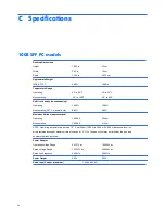
Page 104: ...y be limited by the type and number of options installed Power Adapter Operating Voltage Range Rated Voltage Range Rated line Frequency Power Output Rated Input Current maximum 1 6A 90 VAC Height Width Depth 100B SFF PC Operating Nonoperating Operating Nonoperating 38 7 C max wet bulb Operating Nonoperating 10 62 in 3 93 in 13 69 in 4 8KG 50 to 95 F 22 to 140 F 10 90 5 95 10 000 ft 30 000 ft 90 13...

Reviews: