5.
Remove the optical drive (see
).
6.
Remove the bottom cover (see
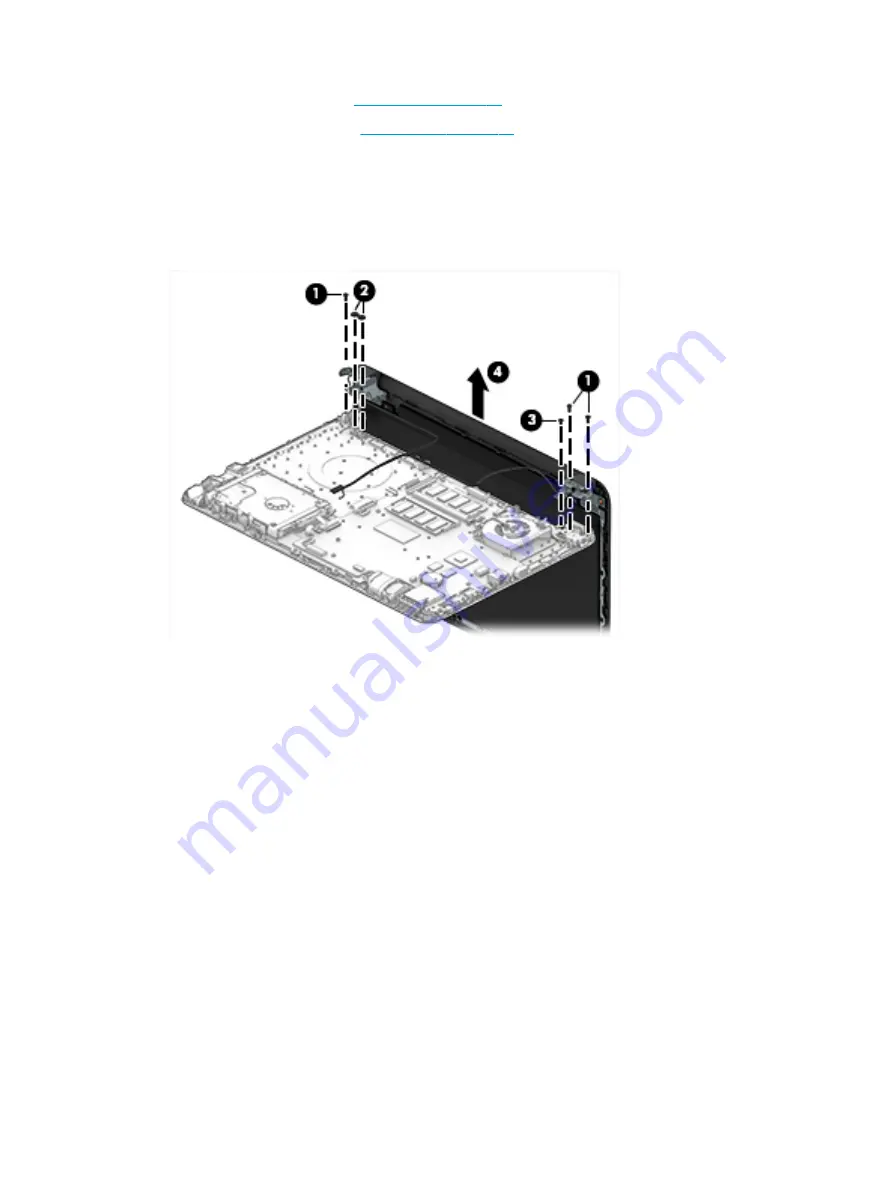
To remove the display assembly:
1.
Remove the three Phillips PM2.5×6.0 screws (1), two Phillips broadhead PM2.0×2.0 screws (2) (on the
right hinge), and one Phillips PM2.5×4.0 screw (3) (on the left hinge) that secures the display assembly
to the computer.
2.
Lift the display from the computer (4).
If it is necessary to replace any of the display assembly subcomponents:
1.
To remove the display bezel:
a.
Remove the two screw covers (1) and two Phillips PM2.5×3.5 screws (2) that secure the display
bezel to the enclosure.
54
Chapter 6 Removal and replacement procedures for Authorized Service Provider parts
Summary of Contents for 14-am0 SERIES
Page 4: ...iv Safety warning notice ...
Page 8: ...viii ...
Page 22: ...14 Chapter 2 External component identification ...
Page 36: ...28 Chapter 5 Removal and replacement procedures for Customer Self Repair parts ...
Page 78: ...70 Chapter 8 Backing up restoring and recovering in Windows 10 ...
Page 96: ...88 Chapter 12 Power cord set requirements ...
Page 98: ...90 Chapter 13 Recycling ...
Page 102: ...94 Index ...


