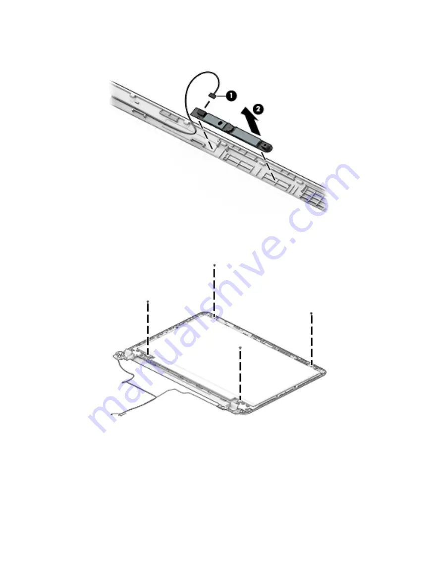
c.
Lift to disengage the adhesive that secures the webcam/microphone module to the display, and
then remove the module (2).
3.
To remove the display panel:
a.
Remove the four Phillips PM2.0×2.4 screws that secure the display panel to the enclosure.
b.
Rotate the display panel off the display enclosure (1) to gain access to the display cable connection
on the back of the panel.
Component replacement procedures
57
Summary of Contents for 14-am0 SERIES
Page 4: ...iv Safety warning notice ...
Page 8: ...viii ...
Page 22: ...14 Chapter 2 External component identification ...
Page 36: ...28 Chapter 5 Removal and replacement procedures for Customer Self Repair parts ...
Page 78: ...70 Chapter 8 Backing up restoring and recovering in Windows 10 ...
Page 96: ...88 Chapter 12 Power cord set requirements ...
Page 98: ...90 Chapter 13 Recycling ...
Page 102: ...94 Index ...


