4.
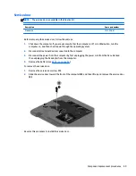
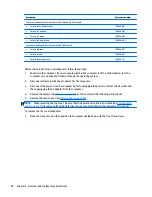
Remove the battery (see
Battery on page 43
).
5.
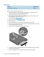
Disconnect the WLAN module antenna cables from the WLAN module (see
WLAN module on page 52
).
6.
Remove the following components:
●
Service door (see
Service door on page 49
)
●
Top cover (see
Top cover/keyboard on page 55
)
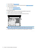
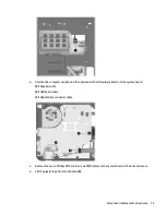
To remove the display assembly:
1.
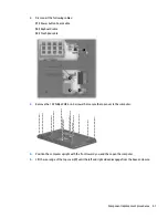
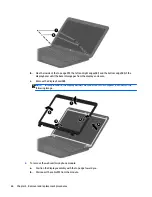
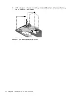
Disengage the adhesive and disconnect the display panel cable
(1)
from the system board.
2.
Remove the display panel cable from its routing path
(2)
.
3.
Release the wireless antenna cables from the clips
(3)
built into the base enclosure.
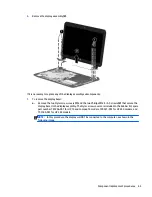
CAUTION:
Support the display assembly when removing the following screws. Failure to support the
display assembly can result in damage to the display assembly and other computer components.
4.
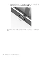
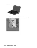
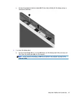
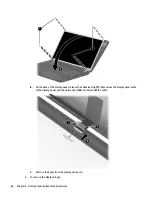
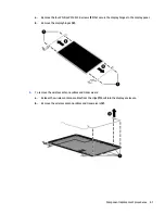
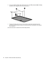
Remove the five Phillips PM2.5×5.0 screws
(1)
that secure the display assembly to the computer.
62
Chapter 4 Removal and replacement procedures
Summary of Contents for 14 TouchSmart
Page 4: ...iv Safety warning notice ...
Page 31: ...3 Illustrated parts catalog Computer major components Computer major components 23 ...
Page 104: ...96 Chapter 5 Using Setup Utility BIOS and HP PC Hardware Diagnostics UEFI in Windows 8 ...
Page 108: ...100 Chapter 6 Using Setup Utility BIOS and System Diagnostics in Windows 7 ...
Page 130: ...122 Chapter 12 Power cord set requirements ...

