a.
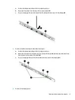
Position the display assembly with the top edge toward you.
b.
Disconnect the cables from the sides of the camera module (1).
c.
Pry up to disengage the camera module from the adhesive that secures it to the display (2).
5.
To remove the IR camera board and/or HD camera board:
a.
Position the display assembly with the top edge toward you.
b.
Disconnect the cable from the ZIF connector outside of the board (1) and disconnect the cable from
the connector on the inside of the board (2).
c.
Pry up to disengage the board from the adhesive that secures it to the display (3).
6.
To remove the display panel:
Component replacement procedures
31
Summary of Contents for 15-cx0000
Page 4: ...iv Safety warning notice ...
Page 8: ...viii ...
Page 32: ...24 Chapter 3 Illustrated parts catalog ...
Page 48: ...40 Chapter 5 Removal and replacement procedures for Authorized Service Provider parts ...
Page 84: ...76 Chapter 7 Backing up restoring and recovering ...
Page 90: ...82 Chapter 8 Using HP PC Hardware Diagnostics ...
Page 96: ...88 Chapter 9 Specifications ...
Page 100: ...92 Chapter 10 Power cord set requirements ...
Page 102: ...94 Chapter 11 Recycling ...
Page 106: ...98 Index ...


