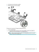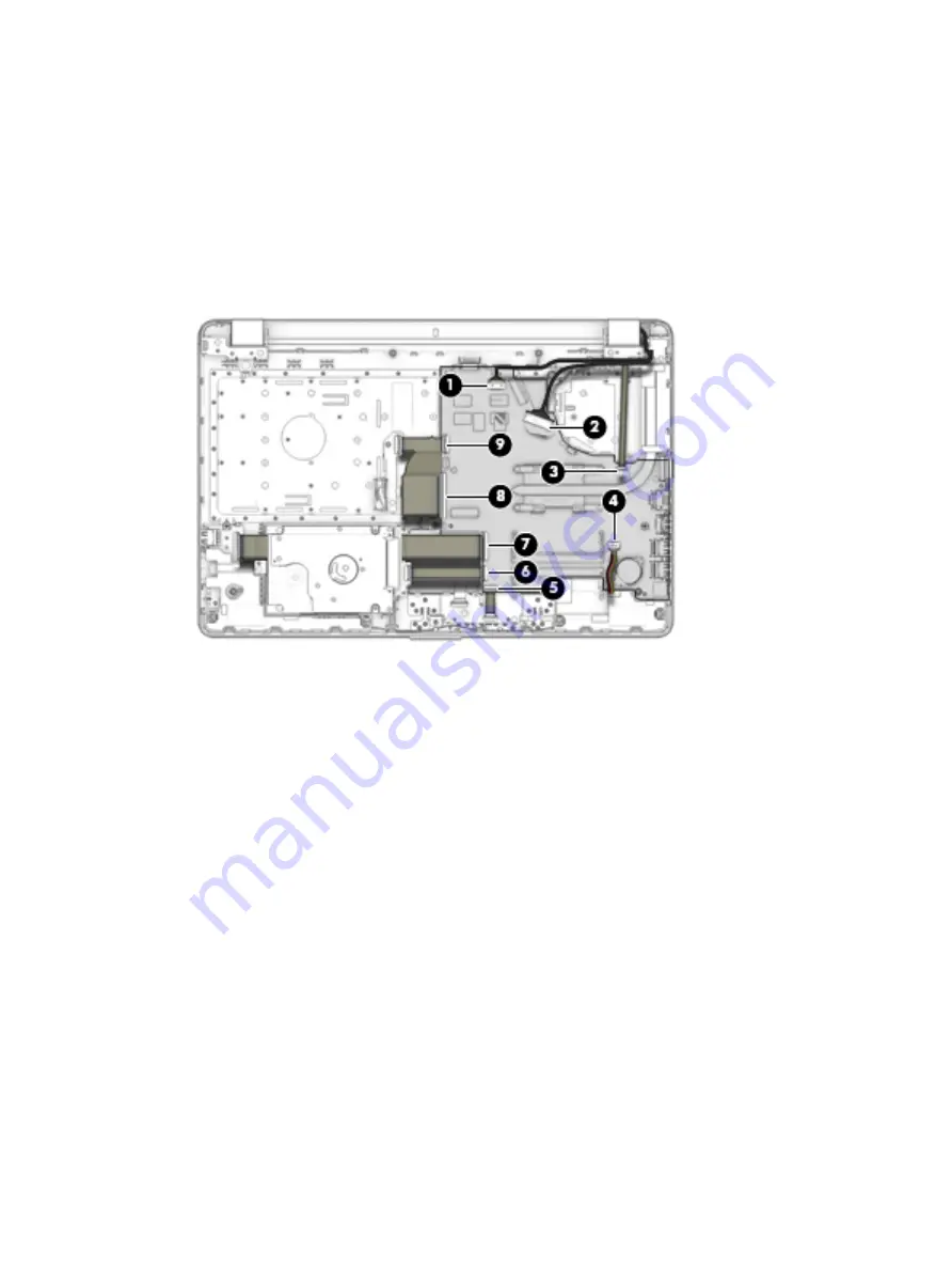
(3): Power button board cable
(4): Speaker cable
(5): TouchPad cable
(6): Hard drive connector cable
(7): USB board cable
(8): Keyboard cable
(9): Optical drive board cable
2.
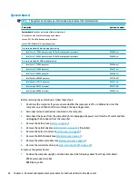
Remove the six Phillips PM2.0×3.0 screws (1) that secure the system board to the computer.
Component replacement procedures
65
Summary of Contents for 250 G6
Page 1: ...HP 250 G6 Notebook PC Maintenance and Service Guide ...
Page 4: ...iv Safety warning notice ...
Page 8: ...viii ...
Page 14: ...6 Chapter 1 Product description ...
Page 26: ...18 Chapter 2 Components ...
Page 88: ...80 Chapter 6 Removal and replacement procedures for Authorized Service Provider parts ...
Page 106: ...98 Chapter 10 Specifications ...
Page 116: ...108 Chapter 12 Power cord set requirements ...
Page 118: ...110 Chapter 13 Recycling ...


