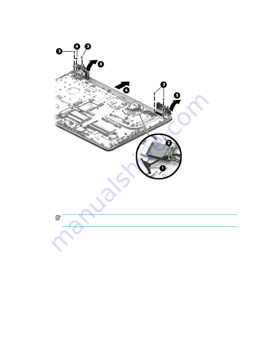
4.
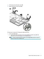
Lift the display to bend the hinges upward (5).
5.
Separate the display from the computer (6).
If it is necessary to replace any of the display assembly subcomponents:
1.
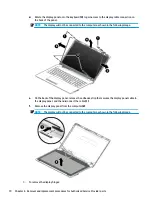
To remove the display bezel:
a.
Flex the inside of the top edge (1), the left and right edges (2), and the bottom edge (3) of the
display bezel until the bezel disengages from the display enclosure.
NOTE:
When removing the bezel from the bottom of the display (3), be careful not to peel the
Mylar from the bottom of the display panel.
Component replacement procedures
67
Summary of Contents for 250 G6
Page 1: ...HP 250 G6 Notebook PC Maintenance and Service Guide ...
Page 4: ...iv Safety warning notice ...
Page 8: ...viii ...
Page 14: ...6 Chapter 1 Product description ...
Page 26: ...18 Chapter 2 Components ...
Page 88: ...80 Chapter 6 Removal and replacement procedures for Authorized Service Provider parts ...
Page 106: ...98 Chapter 10 Specifications ...
Page 116: ...108 Chapter 12 Power cord set requirements ...
Page 118: ...110 Chapter 13 Recycling ...


