background image

o


Cord retention bracket (1) 

o


Jumper cords in the high-voltage model kits (2) 

-or- 


Control unit 

o


0U mounting brackets (2) 

o


1U mounting brackets (2) 

o


Cord retention bracket (1) 


Extension bar hardware (if included) 

This kit might contain extra pieces of hardware for your convenience. 


Model Number 

of 
extension 

bars 

Number of 

single/double 
brackets 

Number of 

extension 
bar power 

cord 

retention 

bands 

Number 

of 
control 

unit tie 

wraps 

252663-
D71 

NA/JPN 

4 8/4  40  6 

252663-
B24 

WW 

2 4/2  40  6 

252663-

D72 
NA/JPN 

4 8/4  40  6 

252663-

B31 
INTL 

4 8/4  40  6 

252663-

B21 
WW 

5 8/4  40  6 

252663-
D73 

NA/JPN 

4 8/4  40  6 

252663-
B32 

INTL 

4 8/4  40  6 

252663-
D74 

NA/JPN 

0 0 

0  6 

252663-
B33 

INTL 

0 0 

0  6 

252663-
D75 

NA/JPN 

0 0 

0  6 

252663-
B34 

INTL 

0 0 

0  6 

AF500A 2 

4/2 

40 

AF501A 2 

4/2 

40 

AF511A 0 

Model Number 

of 

extension 

bars 

Number of 
single/double 

brackets 

Number of 
extension 

bar power 

cord 

retention 
bands 

Number 
of 

control 

unit tie 

wraps 

AF512A 0 

AF513A 0 

AF518A 0 

AF519A 0 


Required tools 

The following tools are required for installation: 


Phillips screwdriver 


T-25 Torx driver 


Cage nut insertion tool (included with your original rack 
hardware) 


Installing the control unit 

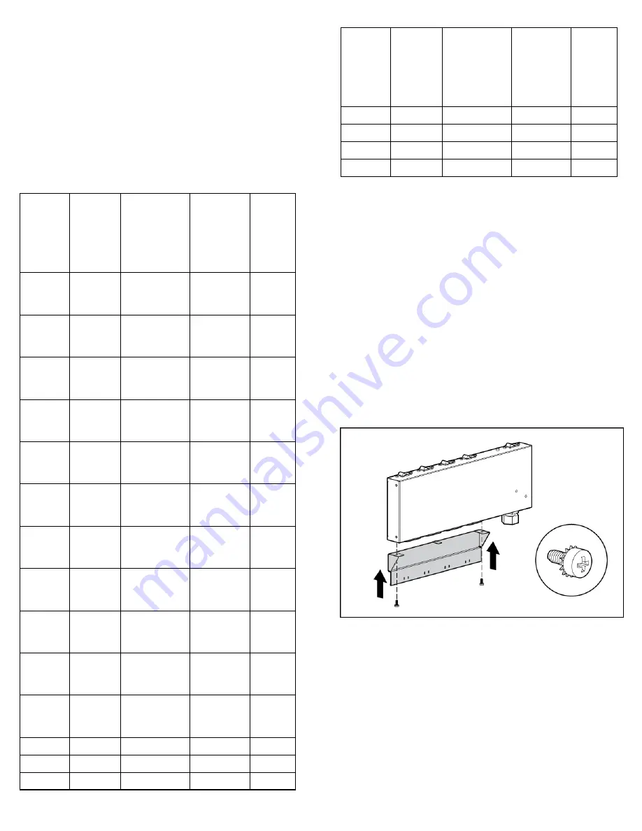
Installing the control unit cord retention 

bracket (if included) 

The control unit cord retention bracket is shown for clarification in the 

following diagram, though installation of the control unit cord 
retention bracket is optional. 


Summary of Contents for 252663-B24 - PDU Power Distribution Strip

Page 1: ...ts circuit breakers move to Off position minimizing downtime Power cord retention Recessed handles to prevent inadvertent power off The extension bars if included provide the following features Multiple power outlets conveniently located for quick and easy equipment power connections Lighted main power indicator Attached 2 m 6 ft input power cords Power cord retention and power cord labeling Modul...

Page 2: ...ceed the total output rating marked on the mPDU WARNING To reduce the risk of personal injury from high leakage current verify earth connection before connecting the power supply The summation of input power for multiple pieces of information technology equipment through the use of power products can result in high leakage currents If the total system leakage current for a system of components exc...

Page 3: ...TL 4 8 4 40 6 252663 D74 NA JPN 0 0 0 6 252663 B33 INTL 0 0 0 6 252663 D75 NA JPN 0 0 0 6 252663 B34 INTL 0 0 0 6 AF500A 2 4 2 40 0 AF501A 2 4 2 40 0 AF511A 0 0 0 6 Model Number of extension bars Number of single double brackets Number of extension bar power cord retention bands Number of control unit tie wraps AF512A 0 0 0 6 AF513A 0 0 0 6 AF518A 0 0 0 6 AF519A 0 0 0 6 Required tools The followin...

Page 4: ...Installing the 0U brackets Installing the 1U brackets ...

Page 5: ... the rack when installing in a square holed rail Installing the control unit in a square and round holed rail NOTE Use the sheet metal mounting screws that are included with this kit when installing in a square and round holed rail Installing the extension bars if included The cord retention brackets are shown for clarification in the following diagrams though installation of the cord retention br...

Page 6: ...Installing the extension bars using single stick mounting brackets Connecting and securing the power cords ...

Page 7: ...n bars and control unit Control unit Total rating of control unit Outlet style Load CB rating Individual outlet rating 228481 001 24 A IEC 320 C19 15 A 12 A 228481 002 24 A IEC 320 C19 15 A 12 A 228481 003 32 A IEC 320 C19 15 A 12 A 228481 004 40 A IEC 320 C19 15 A 12 A 228481 006 16 A IEC 320 C19 10 A 8 A 228481 007 40 A IEC 320 C19 15 A 12 A 228481 008 40 A IEC 320 C19 15 A 12 A 435530 001 41 6 ...

Page 8: ......

Reviews: