Removal and replacement procedures
Maintenance and Service Guide
4–33
Ä
CAUTION:
Support the display assembly when removing the following screws. Failure to support the display
assembly can result in damage to the display assembly and other computer components.
5. Remove the 4 Phillips PM2.0×7.0 screws
1
that secure the display assembly to the base enclosure.
6. Lift the display assembly
2
straight up and remove it.
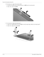
7. If it is necessary to replace the display bezel or any of the display assembly internal components:
a. Remove the hinge covers
1
.
b. Flex the inside edges of the top edge
2
, the left and right sides
3
, and the bottom edge
4
of the display
bezel until the bezel disengages from the display enclosure.
c. Remove the display bezel
5
.
Summary of Contents for 311-1025NR - Mini - Netbook
Page 2: ......
Page 8: ...vii Maintenance and Service Guide Contents ...
Page 14: ...1 6 Maintenance and Service Guide Product description ...
Page 26: ...3 2 Maintenance and Service Guide Illustrated parts catalog Computer major components ...
Page 86: ...4 46 Maintenance and Service Guide Removal and replacement procedures ...
Page 100: ...6 10 Maintenance and Service Guide Specifications ...
Page 122: ...8 8 Maintenance and Service Guide Backup and recovery ...


