Section III
Model 3300A
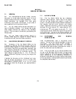
± 25 V, between CKT GND and the
common grounds. OUTPUT GND, SHIELD
GND, and PWR LINE GND should be
shorted together (15).
c.
If more than ± 25 V dc offset is desired,
short CKT GND. OUTPUT GND, and
SHIELD GND together (15). Up to ± 250 V
dc may be applied between this common
ground and PWR LINE GND.
WARNING
WHEN THE OUTPUT GROUND IS
FLOATED ABOVE POWER LINE
GROUND. ALL BNC CONNECTORS
WILL BE AT THE OFFSET VOLTAGE.
3-2
Summary of Contents for 3300A
Page 31: ...Model 3300A Section VI Figure 6 1 3300A Top and Bottom Views 6 2 ...
Page 32: ...Model 3300A Section VI Figure 6 2 Oscillator Circuit Schematic A11 A13 and A14 6 3 ...
Page 33: ...Model 3300A Section VI Figure 6 4 Output Amplifiers Schematic A15 and A16 6 5 6 6 ...
Page 34: ...TM 11 6625 2495 14 P THIS PAGE CURRENTLY NOT AVAILABLE FOR DIGITIZATION PAGE Figure 6 3 6 4 ...
Page 35: ...Model 3300A Section VI Figure 6 5 Power Supply Schematic A12 and A11 6 7 6 8 ...
Page 36: ...Model 3300A Section VI Figure 6 6 J6 Plug In Receptacle 6 9 ...
Page 58: ...SECTION IV REMARKS REFERENCE REMARKS CODE A Visuals B Performance checks D 5 ...
Page 60: ......
Page 61: ...PIN 046175 000 ...


