Model 3300A
Section V
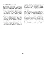
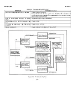
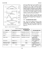
Figure 5-5. Symmetry Adjustment
c.
Measure t1 and adjust A13R22, LOWER
FREQ. SYM., to made t2 = t1. Ref. Figure
5-5. If A13R22 does not have enough
range change A13Q20.
5-31.
Upper Frequency Symmetry Adjust.
(A13R23).
NOTE
Lower Frequency Symmetry must be
set before this adjustment is made.
a.
With the same setup as used for the Lower
Symmetry Adjust, select X100 RANGE and
adjust A13R23 to make t2 equal to t1. The
symmetry error should be < 1%.
b.
Check the symmetry with the dial set to 3
and then again with the dial set to 10. The
symmetry error at both dial settings should
be <1%.
% Symmetry error = t1 -t2 X 100
t1 -t2
5-32.
CURRENT SOURCE ADJUST (A13R24).
NOTE
This adjustment interacts with the
Frequency Symmetry Adjustments
(A13R22 and A13R23): perform the
following adjustment only if the
frequency is not within specified
accuracy(Table 1-1) on the X10 orX.1
RANGE.
a.
Test equipment required: Frequency
Counter (-hp- Model 5245L).
b.
Connect CHANNEL A OUTPUT to
Frequency Counter, and set 3300A controls
as follows:
RANGE switch ........................... X10
FREQUENCY dial ...................... 10
CHANNEL A function ................. SINE
c.
Output frequency should be 100 Hz, *1
minor division on FREQUENCY dial.
d.
Position RANGE switch to X. 1 and
measure output frequency (1 Hz *1 minor
division on FREQUENCY dial.
NOTE
Repeat Frequency Symmetry Adjust
outlined in paragraph 5-29 if A13R24
is adjusted in the following step.
e.
If the frequency is not within specifications
given in step c or d, adjust A13R24
CURRENT SOURCE ADJ for optimum
indication on both X10 and X. I RANGE.
5-33.
DIAL ADJUSTMENT.
a.
Test equipment required: Frequency
Counter (-hp- Model 5245L).
b.
Connect CHANNEL A OUTPUT to
Frequency Counter, and set 3300A control
as follows:
RANGE switch ........................... X10
CHANNEL A function ................. SINE
c.
Loosen dial from hub and adjust the
frequency of 3300A to exactly 100 cps by
rotating the hub. Set the dial to read "1"
and tighten the dial to the hub. Recheck
the frequency.
5-34.
DIAL CALUBRATE.
5-35.
FREQUENCY CALIBRATION ADJUST.
(A13R17).
a.
With same setup as used for 5-33, turn
FREQUENCY dial to "10".
b.
Adjust A13RI7 FREQ CAL ADJ for output
frequency of 1 kHz.
5-36.
X1K RANGE ADJUST (A13C19).
a.
With same setup as used for 5-33, set
RANGE switch to X1K and FREQUENCY
dial to "10".
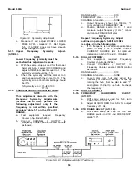
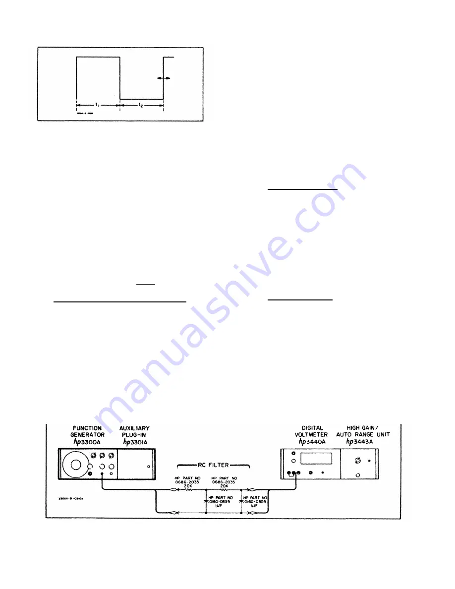
Figure 5-6. DC Output Level Adjust Test Setup
5-5
Summary of Contents for 3300A
Page 31: ...Model 3300A Section VI Figure 6 1 3300A Top and Bottom Views 6 2 ...
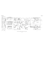
Page 32: ...Model 3300A Section VI Figure 6 2 Oscillator Circuit Schematic A11 A13 and A14 6 3 ...
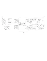
Page 33: ...Model 3300A Section VI Figure 6 4 Output Amplifiers Schematic A15 and A16 6 5 6 6 ...
Page 34: ...TM 11 6625 2495 14 P THIS PAGE CURRENTLY NOT AVAILABLE FOR DIGITIZATION PAGE Figure 6 3 6 4 ...
Page 35: ...Model 3300A Section VI Figure 6 5 Power Supply Schematic A12 and A11 6 7 6 8 ...
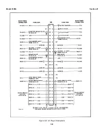
Page 36: ...Model 3300A Section VI Figure 6 6 J6 Plug In Receptacle 6 9 ...
Page 58: ...SECTION IV REMARKS REFERENCE REMARKS CODE A Visuals B Performance checks D 5 ...
Page 60: ......
Page 61: ...PIN 046175 000 ...


