Model 3300A
Section VI
SECTION VI
CIRCUIT DIAGRAMS
6-1.
INTRODUCTION.
6-2.
This section contains schematics and
component location diagrams for the Model 3300A
Function Generator. An adjustment Point Location
diagram is also included.
6-3.
SCHEMATIC DIAGRAMS.
The schematic diagrams are laid out to facilitate ease of
following signal flow and for developing an
understanding of the detailed theory of operation.
Etched circuit board integrity is maintained whenever
possible.
6-4.
COMPONENT LOCATION DIAGRAMS.
The component location diagrams (for each PC Board)
depicts the physical location of components on the
etched circuit board. Figure 6-3 shows the range switch
connections from the main frame of the 3300A to the
plug-in unit.
6-5.
PLUG-IN RECEPTACLE.
6-6.
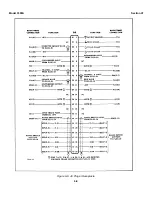
Figure 6-6 shows the connections brought out
from the main frame of the 3300A for use with plug-in
units.
6-1
Summary of Contents for 3300A
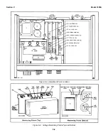
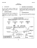
Page 31: ...Model 3300A Section VI Figure 6 1 3300A Top and Bottom Views 6 2 ...
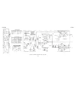
Page 32: ...Model 3300A Section VI Figure 6 2 Oscillator Circuit Schematic A11 A13 and A14 6 3 ...
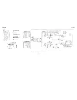
Page 33: ...Model 3300A Section VI Figure 6 4 Output Amplifiers Schematic A15 and A16 6 5 6 6 ...
Page 34: ...TM 11 6625 2495 14 P THIS PAGE CURRENTLY NOT AVAILABLE FOR DIGITIZATION PAGE Figure 6 3 6 4 ...
Page 35: ...Model 3300A Section VI Figure 6 5 Power Supply Schematic A12 and A11 6 7 6 8 ...
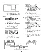
Page 36: ...Model 3300A Section VI Figure 6 6 J6 Plug In Receptacle 6 9 ...
Page 58: ...SECTION IV REMARKS REFERENCE REMARKS CODE A Visuals B Performance checks D 5 ...
Page 60: ......
Page 61: ...PIN 046175 000 ...

