TM 11-6625-2494-14&P
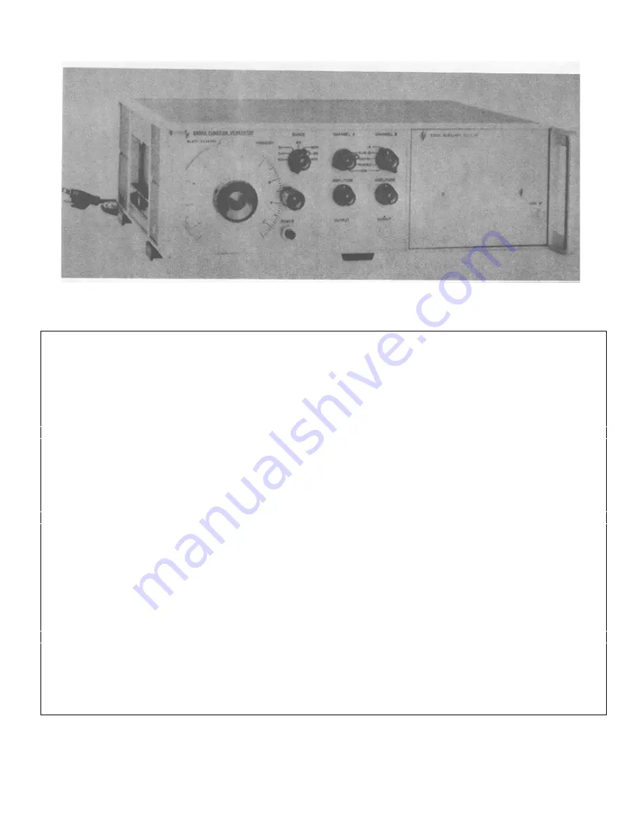
Figure 1-1. Model 3300A Function Generator
Table 1-1. Specifications
AVAILABLE PLUG-IN UNITS:
SINE WAVE DISTORTION: <1%. 0.01 Hz to 10
Model 3301A Auxiliary Plug-In.
kHz; <3%, 10 kHz to 100kHz on the X10K range.
Model 3302A Trigger Plug-In.
Model 3304A Sweep/Offset Plug-In.
SQUARE WAVE RESPONSE: <250 nsec rise and
Model 3305A Sweep Plug-In.
fall time on all ranges; <500 nsec rise and fall
time in -A; <1% sag; <5% overshoot at full out-
OUTPUT WAVEFORMS: Sinusoidal, square, and
put; <1% symmetry error.
triangle selected by panel switch. (Any two
outputs available simultaneously.
TRIANGLE LINEARITY: <1% 0.01 Hz to 10 kHz;
<2%, 10 kHz to 100 kHz at full output; < 1%
FREQUENCY RANGE: 0.01 Hz to 100 kHz in
symmetry error.
seven decade ranges.
SYNC PULSE OUTPUT: > 10 volts peak-to-peak
FREQUENCY RESPONSE: ± 1%, 0.01 Hz to 10
open circuit, <5
µ
sec duration. Sync pulse
kHz; ± 3%, 10 kHz to 100 kHz on the X10K
occurs at crest of sine and triangle wave.
range.
DC STABILITY: Drift: <±0.25%6 of peak-to-peak
DIAL ACCURACY:. ± 1% of maximum dial setting
amplitude over a period of 24 hours. (After 30
(1 minor division) 0. 01 Hz to 10 kHz; ±2% of
minute warmup).
maximum dial setting (2 minor divisions) 10
kHz to 100 kHz. T. C. 0. 1%/°C.
REMOTE FREQUENCY CONTROL: 0 to -10 volts
will linearly change frequency > 1 decade with-
MAXIMUM OUTPUT PER CHANNEL: > 35 volts
in a single range. Frequency resetability with
peak-to-peak open circuit; > 15 volts peak-to-
respect to voltage ±1% of maximum frequency
peak into 600 ohms; > 2 volts peak-to-peak into
on range selected.
50 ohms.
POWER: 115 or 230 volts ±10%, 48 to 440 Hz.
OUTPUT ATTENUATORS (both channels): 40 dB
Less than 50 watts.
range.
DIMENSIONS: (inches and millimeters) 5" high
OUTPUT IMPEDANCE: 600 ohms nominal (both
(127 mm), 16" wide (406 mm), 11" deep
channels) ± 20%.
(279 mm).
1-0
Summary of Contents for 3300A
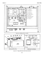
Page 31: ...Model 3300A Section VI Figure 6 1 3300A Top and Bottom Views 6 2 ...
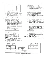
Page 32: ...Model 3300A Section VI Figure 6 2 Oscillator Circuit Schematic A11 A13 and A14 6 3 ...
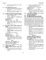
Page 33: ...Model 3300A Section VI Figure 6 4 Output Amplifiers Schematic A15 and A16 6 5 6 6 ...
Page 34: ...TM 11 6625 2495 14 P THIS PAGE CURRENTLY NOT AVAILABLE FOR DIGITIZATION PAGE Figure 6 3 6 4 ...
Page 35: ...Model 3300A Section VI Figure 6 5 Power Supply Schematic A12 and A11 6 7 6 8 ...
Page 36: ...Model 3300A Section VI Figure 6 6 J6 Plug In Receptacle 6 9 ...
Page 58: ...SECTION IV REMARKS REFERENCE REMARKS CODE A Visuals B Performance checks D 5 ...
Page 60: ......
Page 61: ...PIN 046175 000 ...


