3
478A
TM 11-6625-3071-14
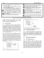
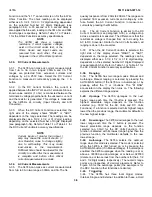
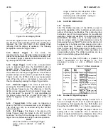
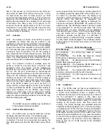
Function and the "4 11" annunciator is on for the 4-Wire
Ohms Function. The ohms reading can be displayed
either as a 5 1/2, 4 1/2, or 3 1/2 digit reading, dependent
on the selected Number Of Digits Displayed (see
paragraph 3-54). A .03 second or a .3 second delay is
also applied before each reading in the 3M ohm and 30M
ohm Ranges, respectively. Refer to Table 1-1 or Table 4-
1 for the Ohms Function’s accuracy specifications.
NOTE
The 3478A will show a negative
resistance if small negative voltages
exist on the circuit under test, or the
Ohms Sense and Input Leads are
reversed from each other. This only
happens in the 4- Wire Ohms Function.
3-30. DC Current Measurements
3-31. The 3478A can make dc current measurements
from 1uA to 3A in two ranges: 300mA and 3A. The
ranges are protected from excessive currents and
voltages by a 3A 250V fuse. Select the DC Current
Function to measure dc currents by pressing the = A
button.
3-32. In the DC Current Function, the current is
applied between the INPUT LO and A Terminals. Since a
known value resistor (.1 ohm) is connected between the
terminals, a voltage proportional to the unknown cur- rent
and the resistor is generated. This voltage is measured
by the 3478A’s dc circuitry (Input Circuitry and A/D
Converter).
3-33. When the DC Current Function is selected, the
right side of the display shows "MADC" or "ADC",
dependent on the range selected. The readings can be
displayed either as a 5½/2, 41/2, or 31/2 digit reading,
depending on the selected Number of Digits Displayed
(see paragraph 3-54). Refer to Table 1-1 or Table 4-1 for
the DC Current Function's accuracy specifications.
NOTE
Current inputs of greater than about I
amp may cause the current shunt’s (.1
ohm Resistor) value to change slightly,
due to self-heating. This may cause
inaccuracies in the measurement.
Sufficient time should be allowed for the
circuitry to settle after the measurement
is complete and before other critical
current measurements are made.
3-34. AC Current Measurements
3-35. The 3478A can make ac current measurements
from 1uA to 3A in two ranges: 300mA and 3A. The fre
quency response is from 20Hz to 20KHz. The ranges are
protected from excessive currents and voltage by a 3A
fuse. Select the AC Current Function to measure ac
currents by pressing the
∼
A button.
3-36. The AC Current Function is similar to the DC
Current Function (see paragraph 3-30); a voltage drop
across a resistor is measured. The difference is that the
resultant ac voltage is changed from ac to dc using the
AC to DC Converter. Similar to the AC Volts Function, all
ranging is done in the converter.
3-37. When the AC Current Function is selected, the
right side of the display shows "MAAC" or "AAC",
dependent on the range selected. The readings can be
displayed either as a 5 1/2, 4 1/2, or 3 1/2 digit reading,
dependent on the selected Number Of Digits Displayed
(see paragraph 3-54). Refer to Table 1-I or Table 4-1 for
the AC Current Function's accuracy specifications.
3-38. Ranging
3-39. The 3478A has two range modes: Manual and
Autorange. Manual ranging is selected by pressing the
AUTO/MAN button (if the 3478A is in Autorange) or by
pressing either the
Ù
or
Ú
buttons. The "M RNG"
annunciator on the display then turns on. The following
explains the different range modes.
3-40. Uprange. The 3478A upranges to the next
higher range each time the
Ù
button is pressed. The
highest selectable range depends on the function
selected (e.g. 300V for the AC Volts and DC Volts
Functions). If a function is selected with its highest range
lower than the previous range, the multimeter defaults to
the new highest range.
3-41. Downrange. The 3478A downranges to the next
lower range each time the
Ú
button is pressed. The
lowest selectable range depends on the function
selected (e.g. 30mV for the DC Volts Function). If a
function is selected with its lowest range higher than the
previous function, the multimeter defaults to the new
lowest range.
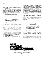
3-42. Autorange. The 3478A selects the optimum
range when this mode is selected. The mode is selected
when the 3478A is first turned on or by pressing the
AUTO/MAN button (if in Manual Range). If Autorange is
enabled, the 3478A upranges when the reading is at or
above ± 303099 and downranges at or below +027000
(delete one or two zeroes from the numbers for the 4 1/2
and 3 1/2 Digit modes, respectively). The numeric range
points are irrespective of decimal placement. Refer to
Figure 3-5 for the autorange points (the example is for
the DCV Function; other functions are similar).
3-43. Triggering
3-44. The 3478A has three local trigger modes:
Internal, Single, and External. In addition to these, a Hold
3-5
Summary of Contents for 3478A
Page 2: ...TM 11 6625 3071 14 A ...
Page 4: ...TM 11 6625 3071 14 C D BLANK ...
Page 12: ...TM 11 6625 3071 14 Table 1 1 Specification 1 2 ...
Page 13: ...TM 11 6625 3071 14 Table 1 1 Specifications Cont 1 3 ...
Page 14: ...TM 11 6625 3071 14 Table 1 1 Specifications Cont 1 4 ...
Page 53: ...TM 11 6625 3071 14 1 ...
Page 54: ...TM 11 6625 3071 14 2 ...
Page 55: ...TM 11 6625 3071 14 3 ...
Page 56: ...TM 11 6625 3071 14 4 ...
Page 87: ...TM 11 6625 3071 14 3478A Figure 7 D 3 Flowchart B 7 D 5 ...
Page 88: ...TM 11 6625 3071 14 3478A Figure 7 D 4 Flowchart C 7 D 6 ...
Page 91: ...TM 11 6625 3071 14 3478A Figure 7 D 6 Flowchart D 7 D 9 ...
Page 111: ...TM 11 6625 3071 14 Figure 7 F 17 3478A Simplified Reference Circuitry 7 F 16 ...
Page 122: ...TM 11 6625 3071 14 Table A 2 A 2 HP IB Worksheet A 4 ...
Page 137: ...TM 11 6625 3071 14 Figure 7 D 2 Flow chart A 7 D 3 ...
Page 139: ...TM 11 6625 3071 14 Figure 7 G 2 3478A Block Diagram 7 G 3 ...
Page 140: ...TM 11 6625 3071 14 Component Locator for Input Circuitry and Ohms Current Source 7 G 4 ...
Page 141: ...TM 11 6625 3071 14 Figure 7 G 3 Input Circuitry and Ohms Current Source 7 G 5 ...
Page 142: ...TM 11 6625 3071 14 F G 6 ...
Page 143: ...TM 11 6625 3071 14 2 Figure 7 G 4 AC to DC Converter 7 G 7 ...
Page 144: ...TM 11 6625 3071 14 Component Locator for A D Converter and Control Logic 7 G 8 ...
Page 145: ...TM 11 6625 3071 14 3 Figure 7 G 5 A D Converter and Control Logic 7 G 9 ...
Page 146: ...TM 11 6625 3071 14 7 G 10 ...
Page 147: ...TM 11 6625 3071 14 4 Figure 7 G 6 Power Supplies 7 G 11 7 G 12 blank ...
Page 148: ......
Page 149: ...PIN NO 057444 ...


