3
478A
TM 11-6625-3071-14
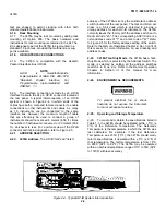
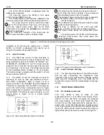
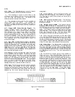
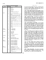
Figure 3-5. Autoranging Points.
and a Fast trigger mode can be selected, but only over
the HP-IB (remote operation). When the multimeter is
triggered, the right most digit on the display blinks
(showing that the display is updated). The following
paragraphs explain the trigger modes.
3-45.
Internal
Trigger.
In this mode, the
measurement cycle is internally initiated and the 3478A
makes the measurements at the maximum reading rate.
The Internal Trigger is selected at instrument turn on or
by pressing the INT/TRIG button.
3-46.
Single Trigger. In this mode, a measurement
cycle is initiated each time the SGL/TRIG button is
pressed. When the button is initially depressed, the
3478A initiates a measurement cycle and then places
the multimeter in the Single Trigger Mode. If the button is
pressed during a measurement cycle (while in the Single
Trigger mode), the 3478A starts a new measurement
cycle. When the cycle is completed, a new cycle can
then be initiated by pressing the Single Trigger button.
3-47.
External Trigger. This mode is selected by
pressing the SGL/TRIG button and operates the same
as the Single Trigger mode. The difference is that the
3478A can be triggered from the External Trigger input
on the rear panel. The input is TTL logic compatible and
the trigger pulse should be at least l00nS wide. The
3478A is triggered on the negative edge of the TTL
pulse.
3-48.
Trigger Hold. In this mode, no triggering is
done by the 3478A (no measurement cycle is initiated).
This mode can only be selected using the 3478A’s
remote operation.
3-49.
Fast Trigger. This trigger is the same as the
Single Trigger except the delays in the ACV and ACI
Functions, and high Ohms Ranges are omitted. This
trigger can only be selected using the remote operation.
NOTE
When the 3478A is in the Single Trigger
mode and an attempt is made to
change
range or function, the left portion of the
display goes blank (except for the
decimal point) until another reading is
taken (instrument triggered).
3-50.
SHIFTED OPERATION
3-51.
General
3-52. The Shifted Operation of the 3478A is used to
expand the capabilities of the multimeter using the same
number of front panel pushbuttons. This is done by using
the bottom row of front panel buttons for two different
operations, shifted and unshifted. An unshifted operation
(AUTO/MAN, INT/TRIG, etc.) is normally selected by
pressing a single button. A shifted operation is done by
first pressing the blue "SHIFT" button (on the right end of
the upper row of buttons) and then pressing one button
(on the lower row). To select a new shifted operation,
press the blue Shift button again and the button for the
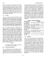
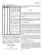
new operation. Table 3-1 lists the shifted operations and
corresponding buttons. The shifted operations are also
shown in blue lettering above the buttons.
3-53.
When the blue Shift button is pressed, the
"SHIFT" annunciator on the display is on. The
annunciator remains on until a different button is
pressed.
Table 3-1. Shifted Operations
3-54.
Number Of Digits Displayed
3-55.
The 3478A can display readings in either 5 1/2, 4
1/2, or 3 1/2 digits. The 5 1/2, 4 1/2, and 3 1/2 digits can
be selected by first pressing the blue Shift button and
then either the AUTO/MAN,
Ù
or
Ú
button, respectively.
3-56.
The Number Of Digits Displayed affects the
reading rate of the multimeter. This is because the
number of digits determines the integration time of the
A/D Converter. In the 4 1/2 digit mode, the integrat;k:.-
3-6
Summary of Contents for 3478A
Page 2: ...TM 11 6625 3071 14 A ...
Page 4: ...TM 11 6625 3071 14 C D BLANK ...
Page 12: ...TM 11 6625 3071 14 Table 1 1 Specification 1 2 ...
Page 13: ...TM 11 6625 3071 14 Table 1 1 Specifications Cont 1 3 ...
Page 14: ...TM 11 6625 3071 14 Table 1 1 Specifications Cont 1 4 ...
Page 53: ...TM 11 6625 3071 14 1 ...
Page 54: ...TM 11 6625 3071 14 2 ...
Page 55: ...TM 11 6625 3071 14 3 ...
Page 56: ...TM 11 6625 3071 14 4 ...
Page 87: ...TM 11 6625 3071 14 3478A Figure 7 D 3 Flowchart B 7 D 5 ...
Page 88: ...TM 11 6625 3071 14 3478A Figure 7 D 4 Flowchart C 7 D 6 ...
Page 91: ...TM 11 6625 3071 14 3478A Figure 7 D 6 Flowchart D 7 D 9 ...
Page 111: ...TM 11 6625 3071 14 Figure 7 F 17 3478A Simplified Reference Circuitry 7 F 16 ...
Page 122: ...TM 11 6625 3071 14 Table A 2 A 2 HP IB Worksheet A 4 ...
Page 137: ...TM 11 6625 3071 14 Figure 7 D 2 Flow chart A 7 D 3 ...
Page 139: ...TM 11 6625 3071 14 Figure 7 G 2 3478A Block Diagram 7 G 3 ...
Page 140: ...TM 11 6625 3071 14 Component Locator for Input Circuitry and Ohms Current Source 7 G 4 ...
Page 141: ...TM 11 6625 3071 14 Figure 7 G 3 Input Circuitry and Ohms Current Source 7 G 5 ...
Page 142: ...TM 11 6625 3071 14 F G 6 ...
Page 143: ...TM 11 6625 3071 14 2 Figure 7 G 4 AC to DC Converter 7 G 7 ...
Page 144: ...TM 11 6625 3071 14 Component Locator for A D Converter and Control Logic 7 G 8 ...
Page 145: ...TM 11 6625 3071 14 3 Figure 7 G 5 A D Converter and Control Logic 7 G 9 ...
Page 146: ...TM 11 6625 3071 14 7 G 10 ...
Page 147: ...TM 11 6625 3071 14 4 Figure 7 G 6 Power Supplies 7 G 11 7 G 12 blank ...
Page 148: ......
Page 149: ...PIN NO 057444 ...


