TM 11-6625-3071-14
3478A
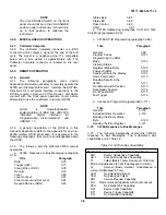
3-76. Data. The Data Message is used to transfer
information between the 3478A and the controller.
a. The message is used to send data to the
multimeter and consists primarily of set-up information
(e.g. DC Volts, 30V Range, etc.). The 3478A is the
Listener and the controller is the Talker.
b. The message is also used by the controller to
receive data from the 3478A. This includes the
multimeter’s output (readings) and status information. In
this case, the 3478A is the Talker and the controller is
the Listener.
3-77. Trigger (GET, Group Execute Trigger). The
Trigger message causes the 3478A to initiate a
measurement cycle. It is an HP-IB Trigger and triggers
the multimeter in any trigger mode, since it has priority
over the other trigger modes. If the 3478A is triggered
during a measurement cycle, the cycle is aborted and a
new cycle is initiated. There may be a delay (up to .5
sec) if a cycle is in progress when the trigger is received.
The multimeter has to be programmed to "listen" to
execute the trigger.
3-78. Clear (DCL or SDC: Device Clear or Selective
Device Clear). A Clear places the 3478A into its turn-on
routine (see paragraph 3-7). In addition, the multimeter’s
address switch (see paragraph 3-92) is read and the
SRQ Mask is set to zero or octal 200 (if the Power-On
SRQ switch is on, see paragraph 3-106). If during the
turn-on routine an error is detected, the hardware error
bit in the serial poll register is set.
3-79. Remote. The Remote Message allows the 3478A
to be controlled over the HP-IB. In remote, the front
panel buttons, except the LOCAL and Front Panel SRQ
buttons, are disabled. The Local and Front Panel SRQ
buttons are only disabled when the 3478A is in remote
and local lockout (see paragraph 3-81). The instrument
state in remote is determined by the local state before
being placed in remote. The RMT annunciator on the
display will also be on with the 3478A in remote.
3-80. Local. This message clears the remote operation
of the 3478A and enables its front panel operation.
Pressing the front panel LOCAL button also places the
multimeter in the local state (if the button has not been
disabled by the Local Lockout Message, see next
paragraph).
3-81. Local Lockout. All the front panel buttons are
disabled with this message, if the 3478A is in remote.
The message is in effect until cleared over the HP-IB or
power is cycled.
3-82. Clear Lockout and Set Local. This message
placed the 3478A into local and the Local Lockout
Message is cleared.
3-83. Require Service (SRQ). The Require Service
Message (SRQ Message) is independent of all other
HPIB activity and is sent on a single line called the SRQ
Line. Its state is either true or false (low=true and high =
false). The 3478A must be programmed to send the
SRQ Message. This is done by programming the SRQ
Mask (see paragraph 3-103). The front panel SRQ
annunciator is on when the 3478A requires service.
3-84. Since more than one device (on the same Bus)
can output the SRQ Message, the devices can be polled
by the controller (by a Serial Poll) to determine if the
3478A (or another device) requires service. The 3478A
then outputs a Status Byte (see paragraph 3-85) which
shows for what reason the multimeter requires service.
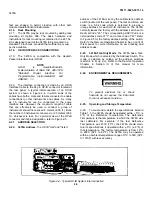
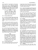
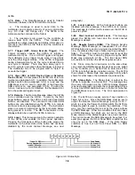
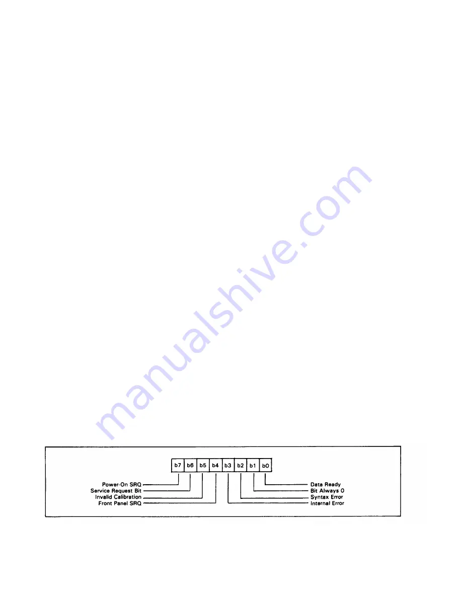
3-85. Status Byte. The Status Byte is output by the
3478A in response to a Serial Poll. The message has
the same information as the 3478A’s Status Register
(see next paragraph), and sets the corresponding bit true
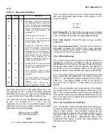
for any true SRQ condition shown in Table 3-4 (whether
the SRQ Mask is set or not). The bit is represented in
Figure 3-6.
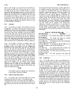
3-86. The 3478A can require service if any condition in
Table 3-4 is true. Since the SRQ Mask must be set to
output the Require Service Message (except for bit 7,
which is set by the Power-On SRQ switch), the 3478A’s
Status Register is used to monitor the conditions. This
way, only the condition that is set by the mask outputs
the SRQ Message. Other true conditions that can cause
an SRQ Message, but which are not set by the SRQ
Mask, remain in the Status Register as a true condition.
They will not cause the SRQ Message to be output. For
example, suppose the Front Panel SRQ condition is the
only one set in the SRQ Mask. If the Data Ready
condition is true, but not Front Panel SRQ, no SRQ
Message
Figure 3-6. Status Byte
3-9
Summary of Contents for 3478A
Page 2: ...TM 11 6625 3071 14 A ...
Page 4: ...TM 11 6625 3071 14 C D BLANK ...
Page 12: ...TM 11 6625 3071 14 Table 1 1 Specification 1 2 ...
Page 13: ...TM 11 6625 3071 14 Table 1 1 Specifications Cont 1 3 ...
Page 14: ...TM 11 6625 3071 14 Table 1 1 Specifications Cont 1 4 ...
Page 53: ...TM 11 6625 3071 14 1 ...
Page 54: ...TM 11 6625 3071 14 2 ...
Page 55: ...TM 11 6625 3071 14 3 ...
Page 56: ...TM 11 6625 3071 14 4 ...
Page 87: ...TM 11 6625 3071 14 3478A Figure 7 D 3 Flowchart B 7 D 5 ...
Page 88: ...TM 11 6625 3071 14 3478A Figure 7 D 4 Flowchart C 7 D 6 ...
Page 91: ...TM 11 6625 3071 14 3478A Figure 7 D 6 Flowchart D 7 D 9 ...
Page 111: ...TM 11 6625 3071 14 Figure 7 F 17 3478A Simplified Reference Circuitry 7 F 16 ...
Page 122: ...TM 11 6625 3071 14 Table A 2 A 2 HP IB Worksheet A 4 ...
Page 137: ...TM 11 6625 3071 14 Figure 7 D 2 Flow chart A 7 D 3 ...
Page 139: ...TM 11 6625 3071 14 Figure 7 G 2 3478A Block Diagram 7 G 3 ...
Page 140: ...TM 11 6625 3071 14 Component Locator for Input Circuitry and Ohms Current Source 7 G 4 ...
Page 141: ...TM 11 6625 3071 14 Figure 7 G 3 Input Circuitry and Ohms Current Source 7 G 5 ...
Page 142: ...TM 11 6625 3071 14 F G 6 ...
Page 143: ...TM 11 6625 3071 14 2 Figure 7 G 4 AC to DC Converter 7 G 7 ...
Page 144: ...TM 11 6625 3071 14 Component Locator for A D Converter and Control Logic 7 G 8 ...
Page 145: ...TM 11 6625 3071 14 3 Figure 7 G 5 A D Converter and Control Logic 7 G 9 ...
Page 146: ...TM 11 6625 3071 14 7 G 10 ...
Page 147: ...TM 11 6625 3071 14 4 Figure 7 G 6 Power Supplies 7 G 11 7 G 12 blank ...
Page 148: ......
Page 149: ...PIN NO 057444 ...


