TM 11-6625-3071-14
3478A
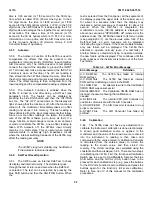
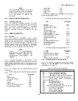
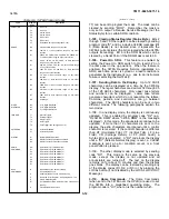
Table 3-5. 3478A Address Codes
3-98. 3478A HP-IB Programming
3-99. General. The following paragraphs explain how to
program the 3478A over the HP-IB. The information is
given using the HP-IB format, rather than controller
dependent language. If the information is desired using
controller dependent language, refer to the 3478A’s
Operator’s Manual.
3-100. Programming the 3478A is done by DATA
messages. Set-up information (Range, Function, etc.) is
DATA sent by the controller and is done using program
codes. The DATA received by the controller (from the
3478A) is measurement data, and other data like the
Status Byte and the five bytes from the Output Binary
Status Byte.
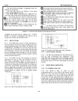
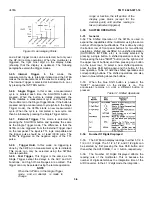
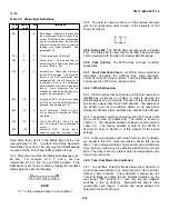
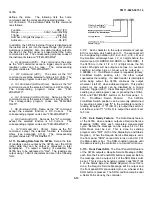
3-101. Program Codes. All the program codes for the
3478A are listed in Table 3-6. The 3478A must be in
"remote" and "listen" to receive the codes (the RMT and
LSTN annunciators are on when the 3478A is in remote
and listening). An example is as follows:
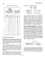
3-102. The Program Codes are a series of 7-bit ASCII
characters (the parity bit is ignored). All lower case
characters, spaces, commas, and semicolons are
ignored (they may be used with the codes as
separators). All null characters, carriage return, line
feed, form feed, vertical tab, and horizontal tab
characters are also ignored. Other characters which are
not included in Table 3-6, cause a Syntax Error (bit 2 in
the Status Register set). In addition, a Syntax Error is
caused if the characters are sent in a different order than
shown in the table (e.g. "IF" causes a Syntax Error).
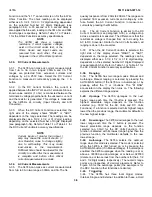
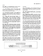
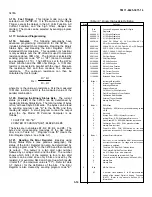
3-103. Programming the SRQ Mask. The SRQ Mask
must be set for the 3478A to output a Require Service
Message. Setting the SRQ Mask will not set the bits in
the Status Byte; these bits are automatically set (except
bit 6) when any corresponding require service condition
is true. For example, you wish to know if the multimeter
has received an incorrect program code (Syntax Error) or
has an internal failure (Internal Error). If the conditions
are true, bits 2 and 3 of the Status Byte are set; but no
Require Service Message is output. The message will
not be output until the SRQ Mask is set to the
corresponding bits of the Status Byte (which are bits 2
and 3). Since the mask is to be set in octal, the resultant
code for the bits is "14". The mask is set by sending
"Mdd", where dd is-the octal code for the bits. This is
shown
in the following example.
3-104. Only bits 0 to 5 can be set by programming the
SRQ Mask. Bit 6 of the Status Byte is set whenever the
Require Service Message is output and bit 7 is set by the
Power-On SRQ switch on the rear panel (see paragraph
3-105). Because of this, only a two digit octal code (00
to
3-11
Summary of Contents for 3478A
Page 2: ...TM 11 6625 3071 14 A ...
Page 4: ...TM 11 6625 3071 14 C D BLANK ...
Page 12: ...TM 11 6625 3071 14 Table 1 1 Specification 1 2 ...
Page 13: ...TM 11 6625 3071 14 Table 1 1 Specifications Cont 1 3 ...
Page 14: ...TM 11 6625 3071 14 Table 1 1 Specifications Cont 1 4 ...
Page 53: ...TM 11 6625 3071 14 1 ...
Page 54: ...TM 11 6625 3071 14 2 ...
Page 55: ...TM 11 6625 3071 14 3 ...
Page 56: ...TM 11 6625 3071 14 4 ...
Page 87: ...TM 11 6625 3071 14 3478A Figure 7 D 3 Flowchart B 7 D 5 ...
Page 88: ...TM 11 6625 3071 14 3478A Figure 7 D 4 Flowchart C 7 D 6 ...
Page 91: ...TM 11 6625 3071 14 3478A Figure 7 D 6 Flowchart D 7 D 9 ...
Page 111: ...TM 11 6625 3071 14 Figure 7 F 17 3478A Simplified Reference Circuitry 7 F 16 ...
Page 122: ...TM 11 6625 3071 14 Table A 2 A 2 HP IB Worksheet A 4 ...
Page 137: ...TM 11 6625 3071 14 Figure 7 D 2 Flow chart A 7 D 3 ...
Page 139: ...TM 11 6625 3071 14 Figure 7 G 2 3478A Block Diagram 7 G 3 ...
Page 140: ...TM 11 6625 3071 14 Component Locator for Input Circuitry and Ohms Current Source 7 G 4 ...
Page 141: ...TM 11 6625 3071 14 Figure 7 G 3 Input Circuitry and Ohms Current Source 7 G 5 ...
Page 142: ...TM 11 6625 3071 14 F G 6 ...
Page 143: ...TM 11 6625 3071 14 2 Figure 7 G 4 AC to DC Converter 7 G 7 ...
Page 144: ...TM 11 6625 3071 14 Component Locator for A D Converter and Control Logic 7 G 8 ...
Page 145: ...TM 11 6625 3071 14 3 Figure 7 G 5 A D Converter and Control Logic 7 G 9 ...
Page 146: ...TM 11 6625 3071 14 7 G 10 ...
Page 147: ...TM 11 6625 3071 14 4 Figure 7 G 6 Power Supplies 7 G 11 7 G 12 blank ...
Page 148: ......
Page 149: ...PIN NO 057444 ...


