TM 11-6625-3071-14
SECTION IV
PERFORMANCE TEST AND CALIBRATION
4-1. INTRODUCTION
4-2. This section of the manual has the Performance
Tests and Calibration Procedures used to verify the
3478A’s accuracy specifications, and to calibrate the
multimeter to those specifications. A summary of the
specifications to which the 3478A is tested and calibrated
is listed in Table 4-1. The complete specifications are in
Table 1-1. All tests and calibrations are made without
removing any instrument ’covers.
4-3. Since Performance Tests are normally performed
after calibration, the tests are included in the Calibration
Procedures. The procedures are set up in such a way
that the Performance Tests can be ignored, if so desired.
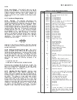
Table 4-1. Abbreviated Specifications Table
DC Volts Function (accuracy =
±
(% of reading - number of counts))
Range 24 Hour Limits 90 Day Limit 1 Year Limits
30mV 0.027 + 35 0.03 + 41 0.04 + 41
300mV 0.005 + 4 0.0074 + 5 0.02 + 5
3V 0.0034 + 2 0.0059 + 2 0.0188 + 2
30V 0.005 + 3 0.0074 + 3 0.02 + 3
300V 0.0055 + 2 0.0076 + 2 0.02 + 2
DC Carrot Function (accuracy =
±
(% of r number of counts)
Range 90 Day Limits 1 Year Limits
300mA 0 11 + 40 0.15 + 40
3A<1A 0.14 + 6 0.17 + 6
3A>1A 1.0 + 30 1 0 + 30
Ohms Function (accuracy =
±
(% of r number of counts)
Range 24 Hour Limits 90 Day Limits 1 Year Limits
30 0.023 + 35 0.0027 + 41 0.034 + 41
300 0.0045 + 4 0.012 + 5 0.017 + 5
3K 0.0035 + 2 0.011 + 2 0.016 + 2
30K 0.0035 + 2 0.011 + 2 0.016 + 2
300K 0.0035 + 2 0.011 + 2 0.016 + 2
3M 0.0052 + 2 0.011 + 2 0.016 + 2
30M 0.036 + 2 0.066 + 2 0.078 + 2
AC Volt Function 1 Year Limits (accuracy =
±
(% of r number of
counts)
Frequency 300 mV Range 3V Range 30V Range 300V Range
20Hz 50Hz 1.14 + 163 1.14 + 102 1.14 + 102 1.18 + 102
50Hz 100Hz 0.46 + 163 0.46 + 103 0 46 + 102 0.5 + 102
100Hz 20KHz 0.29 + 163 0.26 + 102 0.26 +102 0.33 + 102
20KHz 50KHz 0.56 + 247 0.41 + 180 0.37 + 180 0.56 + 180
50KHz 100KHz 1.74 + 882 1.05 + 825 0.84 + 825 1.26 + 825
100KHz 300KHz N/A 10.1 + 3720 N/A N,A
AC Current Function 1 Year Limits (accuracy -
±
(% of r Number of
counts))
Frequency 300mA Range 3A Range
20Hz 50Hz 1.54 + 163 2.24 + 163
50Hz 1KHz 0.81 + 163 1.5 + 163
1KHz 10KHz 0.72 + 163 1.42 + 163
10KHz 20KHz 0.86 + 163 1.56 + 163
4-4. EQUIPMENT REQUIRED
4-5. All the required test equipment for the Performance
Tests and Calibration Procedures are listed in Table 4-2
(Recommended Test Equipment). The equipment used for
the individual tests is also listed at the beginning of each test
procedure. If any of the recommended equipment is not
available, use substitute equipment. A short description of
the required equipment and the critical specifications
necessary to do the test and calibration procedures is in the
following paragraphs. This information may be helpful in
choosing substitute equipment.
4-6. DC Volts Test and Calibration
4-7. The DC Volts Test and Calibration (DC Volts Function)
requires a very accurate Digital Voltmeter (like the 3456A) as
the Standard. The Digital Voltmeter must be calibrated to its
24 hour dc volts specifications before calibrating and testing
the 3478A (i.e. the 3478A is tested and calibrated within 24
hours after the Digital Voltmeter, used as the standard, has
been calibrated). It is recommended that the Digital Voltmeter
be calibrated in the same temperature environment and leave
it in the environment in which the 3478A is to be calibrated
and tested (e.g. the 3478A’s Reference Temperature, see
Paragraph 4-39). In addition to the Digital Voltmeter, a DC
Volts Standard is required to be used as a very stable voltage
source. The following lists the required equipment and
recommended models.
4-8. Digital Voltmeter. The recommended Digital Voltmeter
is an -hp- Model 3456A. The critical requirements are as
follows:
a. Required voltage range is from 30mV to 300V dc.
b. Accuracy and stability requirements in a 24 hour period
is as follows:
±
.004% for the 30V and 300V Ranges
±.005% for the 300mV and 3V Ranges
±.025% for the 30mV Range
4-9. DC Volts Standard. The DC Volts Standard chosen is
a Systron Donner Model M107 Precision Voltage Source.
The critical requirements are as follows:
4-1
Summary of Contents for 3478A
Page 2: ...TM 11 6625 3071 14 A ...
Page 4: ...TM 11 6625 3071 14 C D BLANK ...
Page 12: ...TM 11 6625 3071 14 Table 1 1 Specification 1 2 ...
Page 13: ...TM 11 6625 3071 14 Table 1 1 Specifications Cont 1 3 ...
Page 14: ...TM 11 6625 3071 14 Table 1 1 Specifications Cont 1 4 ...
Page 53: ...TM 11 6625 3071 14 1 ...
Page 54: ...TM 11 6625 3071 14 2 ...
Page 55: ...TM 11 6625 3071 14 3 ...
Page 56: ...TM 11 6625 3071 14 4 ...
Page 87: ...TM 11 6625 3071 14 3478A Figure 7 D 3 Flowchart B 7 D 5 ...
Page 88: ...TM 11 6625 3071 14 3478A Figure 7 D 4 Flowchart C 7 D 6 ...
Page 91: ...TM 11 6625 3071 14 3478A Figure 7 D 6 Flowchart D 7 D 9 ...
Page 111: ...TM 11 6625 3071 14 Figure 7 F 17 3478A Simplified Reference Circuitry 7 F 16 ...
Page 122: ...TM 11 6625 3071 14 Table A 2 A 2 HP IB Worksheet A 4 ...
Page 137: ...TM 11 6625 3071 14 Figure 7 D 2 Flow chart A 7 D 3 ...
Page 139: ...TM 11 6625 3071 14 Figure 7 G 2 3478A Block Diagram 7 G 3 ...
Page 140: ...TM 11 6625 3071 14 Component Locator for Input Circuitry and Ohms Current Source 7 G 4 ...
Page 141: ...TM 11 6625 3071 14 Figure 7 G 3 Input Circuitry and Ohms Current Source 7 G 5 ...
Page 142: ...TM 11 6625 3071 14 F G 6 ...
Page 143: ...TM 11 6625 3071 14 2 Figure 7 G 4 AC to DC Converter 7 G 7 ...
Page 144: ...TM 11 6625 3071 14 Component Locator for A D Converter and Control Logic 7 G 8 ...
Page 145: ...TM 11 6625 3071 14 3 Figure 7 G 5 A D Converter and Control Logic 7 G 9 ...
Page 146: ...TM 11 6625 3071 14 7 G 10 ...
Page 147: ...TM 11 6625 3071 14 4 Figure 7 G 6 Power Supplies 7 G 11 7 G 12 blank ...
Page 148: ......
Page 149: ...PIN NO 057444 ...

