TM 11-6625-3071-14
3478A
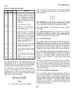
Figure 4-5. AC Current Accuracy Test and Calibration
AC-DC Current Calibrator to the IA Range. Check and
record the 3478A’s reading.
j. Remove the AC Calibrator from the AC-DC Current
Calibrator. Remove the current calibrator from the
3478A. This completes the AC Current Test. If any test
fails, try calibrating the instrument (go to paragraph 4-
94). If the test still fails, go to this manual’s Section VII
for troubleshooting.
4-69. Ohms Test
4-70. The Ohms Test should only be done in the ohms
function in which the 3478A was last calibrated. If, for
example, the 3478A was last calibrated in the 4-Wire
Ohms Function, perform the Ohms Test in the 4-Wire
Ohms Function. If the 3478A was last calibrated in the
2-Wire Ohms Function, perform the Ohms Test in the
3478A
2-Wire Ohms Function. In addition, the same test
connections or test leads used to calibrate the 3478A in
the 2-Wire Ohms Function must also be used when
testing the multimeter in that function. This is because
the impedance of the test leads is canceled out when the
multimeter is calibrated (in the 2-Wire Ohms Function). A
different set of test leads can have different impedances
which show up as an ohms test error.
4-71. The Ohms Function of the 3478A can be tested
using either full scale or 1/3 scale inputs (e.g. 3K ohm or
1K ohm resistors to check the 3K ohm Range). Because
of this, both test limits are in Table 4-7 and on the Ohms
Performance Test Card. The test step numbers (on the
Test Card) shown in parenthesis are for the 1/3 scale
tests. When testing the 3478A, make sure the test leads
used to connect the standard resistor to the 3478A’s
INPUT Terminals are as short as possible. This is to
prevent the leads from picking up any noise, which could
give an invalid reading.
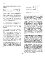
4-72. If the 3478A is to be tested in the 2-Wire Ohms
Function, all test resistors are applied to the 3478A’s
INPUT Terminals. If the 4-Wire Ohms Function is to be
tested, short the INPUT Terminals and connect the test
resistors to the terminals, as shown in Figure 4-6 and
Figure 4-7, respectively.
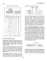
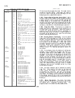
4-73. The Ohms Test limits are printed on the Ohms
Test Card and in Table 4-7. Each step on the test card
corresponds to a step in the procedure with each step
number shown in parenthesis in the procedure.
4-74. Equipment Required. The following is the
required test equipment for the Ohms Test.
Table 4-7. Ohms Test Limits
4-10
Summary of Contents for 3478A
Page 2: ...TM 11 6625 3071 14 A ...
Page 4: ...TM 11 6625 3071 14 C D BLANK ...
Page 12: ...TM 11 6625 3071 14 Table 1 1 Specification 1 2 ...
Page 13: ...TM 11 6625 3071 14 Table 1 1 Specifications Cont 1 3 ...
Page 14: ...TM 11 6625 3071 14 Table 1 1 Specifications Cont 1 4 ...
Page 53: ...TM 11 6625 3071 14 1 ...
Page 54: ...TM 11 6625 3071 14 2 ...
Page 55: ...TM 11 6625 3071 14 3 ...
Page 56: ...TM 11 6625 3071 14 4 ...
Page 87: ...TM 11 6625 3071 14 3478A Figure 7 D 3 Flowchart B 7 D 5 ...
Page 88: ...TM 11 6625 3071 14 3478A Figure 7 D 4 Flowchart C 7 D 6 ...
Page 91: ...TM 11 6625 3071 14 3478A Figure 7 D 6 Flowchart D 7 D 9 ...
Page 111: ...TM 11 6625 3071 14 Figure 7 F 17 3478A Simplified Reference Circuitry 7 F 16 ...
Page 122: ...TM 11 6625 3071 14 Table A 2 A 2 HP IB Worksheet A 4 ...
Page 137: ...TM 11 6625 3071 14 Figure 7 D 2 Flow chart A 7 D 3 ...
Page 139: ...TM 11 6625 3071 14 Figure 7 G 2 3478A Block Diagram 7 G 3 ...
Page 140: ...TM 11 6625 3071 14 Component Locator for Input Circuitry and Ohms Current Source 7 G 4 ...
Page 141: ...TM 11 6625 3071 14 Figure 7 G 3 Input Circuitry and Ohms Current Source 7 G 5 ...
Page 142: ...TM 11 6625 3071 14 F G 6 ...
Page 143: ...TM 11 6625 3071 14 2 Figure 7 G 4 AC to DC Converter 7 G 7 ...
Page 144: ...TM 11 6625 3071 14 Component Locator for A D Converter and Control Logic 7 G 8 ...
Page 145: ...TM 11 6625 3071 14 3 Figure 7 G 5 A D Converter and Control Logic 7 G 9 ...
Page 146: ...TM 11 6625 3071 14 7 G 10 ...
Page 147: ...TM 11 6625 3071 14 4 Figure 7 G 6 Power Supplies 7 G 11 7 G 12 blank ...
Page 148: ......
Page 149: ...PIN NO 057444 ...

