TM 11-6625-3071-14
SERVICE GROUP B
AC VOLTS AND AC CURRENT TROUBLESHOOTING
Service Group B Contents
Title
Paragraph
Introduction ............................................................................7-B-1
AC Volts Troubleshooting ......................................................7-B-3
Overload, Floating, or Noisy Readings on All Ranges...........7-B-5
Inaccurate Readings on All Ranges................................7-B-8
Overload, Inaccurate, Floating or Noisy Readings
on Some Ranges ....................................................7-B-10
AC Current Troubleshooting ................................................7-B-12
Overload Protection Circuitry Troubleshooting ....................7-B-14
Checking the A/D Controller ................................................7-B-16
7-B-1. INTRODUCTION
7-B-2. This Service Group has the AC Volts and AC
Current troubleshooting information for the 3478A and is
symptoms oriented (i.e., what fails). Before
troubleshooting for AC Volts or AC Current Failures,
make sure the 3478A’s DC Volts and DC Current
Functions are operating correctly (go to Service Group A,
if the functions fail). These functions must be good,
before the AC Volts and AC Current Functions can
operate.
CAUTION
The instrument contains CMOS Integrated
Circuits (e.g. U102) which are extremely
susceptible to failures due to static
discharge. It is especially important that
grounded tools and wrist straps be used
when handling or troubleshooting these
components.
7-B-3. AC VOLTS TROUBLESHOOTING
7-B-4. An AC Volts Failure can be Overload, Inaccurate,
Floating, or Noisy Readings on all or some ranges. The
following paragraphs have the failures and
troubleshooting procedures (go to paragraph 7-31 for a
description of these failures). Unless otherwise
specified, refer to Schematic 2 for the following
troubleshooting procedures.
7-B-5. Overload, Floating, or Noisy Readings on All
Ranges
7-B-6. An overload reading can be caused if one of the
amplifiers or the RMS Converter in the AC to DC Con-
verter is saturated. A floating reading can be caused if
there is an open circuit in the AC to DC Converter. Noisy
readings can be caused by any of the amplifiers in the
converter.
7-B-7. Before troubleshooting the AC to DC Converter,
make sure relay K104 (see Schematic 1) is good and is
energized (5V dc across the coil). If the relay is not
energized, U102 may be defective. Before replacing
U102, make sure the A/D Controller (U462) is good. Go
to paragraph 7-B-16 to check U462. If K104 is good, do
the following procedure.
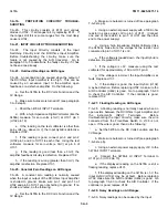
a. Set the 3478A to the AC Volts Function and the
3V Range.
b. Apply a stable 3V at 1KHz sine wave to the
3478A’s INPUT Terminals.
c. Using a stable Digital Voltmeter (like the 3456A),
measure for approxi 3V dc at jumper JM302.
d. If the reading is a 3V dc, do the
following:
1. Apply 1V at 1KHz to the INPUT Terminals.
2. If the test voltmeter now reads a 1V
dc at JM302, the AC to DC Converter is good.
Make sure the DC Volts Function is operating
correctly.
3. If the DC Volts Function is good, replace the
A/D Hybrid (U403).
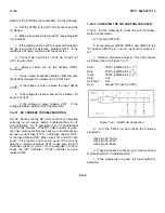
e. If the reading is other than approxi3V or
noisy, measure for approximately .12V ac at jumper
JM303. Make sure the reading on the test voltmeter is
stable.
7-B-1
Summary of Contents for 3478A
Page 2: ...TM 11 6625 3071 14 A ...
Page 4: ...TM 11 6625 3071 14 C D BLANK ...
Page 12: ...TM 11 6625 3071 14 Table 1 1 Specification 1 2 ...
Page 13: ...TM 11 6625 3071 14 Table 1 1 Specifications Cont 1 3 ...
Page 14: ...TM 11 6625 3071 14 Table 1 1 Specifications Cont 1 4 ...
Page 53: ...TM 11 6625 3071 14 1 ...
Page 54: ...TM 11 6625 3071 14 2 ...
Page 55: ...TM 11 6625 3071 14 3 ...
Page 56: ...TM 11 6625 3071 14 4 ...
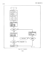
Page 87: ...TM 11 6625 3071 14 3478A Figure 7 D 3 Flowchart B 7 D 5 ...
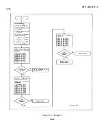
Page 88: ...TM 11 6625 3071 14 3478A Figure 7 D 4 Flowchart C 7 D 6 ...
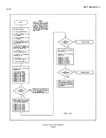
Page 91: ...TM 11 6625 3071 14 3478A Figure 7 D 6 Flowchart D 7 D 9 ...
Page 111: ...TM 11 6625 3071 14 Figure 7 F 17 3478A Simplified Reference Circuitry 7 F 16 ...
Page 122: ...TM 11 6625 3071 14 Table A 2 A 2 HP IB Worksheet A 4 ...
Page 137: ...TM 11 6625 3071 14 Figure 7 D 2 Flow chart A 7 D 3 ...
Page 139: ...TM 11 6625 3071 14 Figure 7 G 2 3478A Block Diagram 7 G 3 ...
Page 140: ...TM 11 6625 3071 14 Component Locator for Input Circuitry and Ohms Current Source 7 G 4 ...
Page 141: ...TM 11 6625 3071 14 Figure 7 G 3 Input Circuitry and Ohms Current Source 7 G 5 ...
Page 142: ...TM 11 6625 3071 14 F G 6 ...
Page 143: ...TM 11 6625 3071 14 2 Figure 7 G 4 AC to DC Converter 7 G 7 ...
Page 144: ...TM 11 6625 3071 14 Component Locator for A D Converter and Control Logic 7 G 8 ...
Page 145: ...TM 11 6625 3071 14 3 Figure 7 G 5 A D Converter and Control Logic 7 G 9 ...
Page 146: ...TM 11 6625 3071 14 7 G 10 ...
Page 147: ...TM 11 6625 3071 14 4 Figure 7 G 6 Power Supplies 7 G 11 7 G 12 blank ...
Page 148: ......
Page 149: ...PIN NO 057444 ...

