3478A
TM 11-6625-3071-14
7-C-14. Floating Reading on All or Some Ranges
7-C-15. A Floating Reading is normally caused by an
open circuit between the INPUT Terminals and the
DC/Ohms Input Amplifier. Make sure the DC Volts
Function is operating correctly, before suspecting an
ohms failure. If the failure shows up in the Ohms
Function only, U102 may be defective. Before replacing
U102, make sure the A/D Controller (U462) is good. Go
to paragraph 7-C-24 to check U462.
7-C-16. Overload, Noise, or Constant Zero Readings
on Some Ranges
7-C-17. Failures on some ranges can only be caused by
the Input Hybrid U102. This is because the hybrid is
used to configure the current source for the different
ranges. If at least one range is good, the Ohms Current
Source is operating. Before replacing U102, make sure
it receives the correct information from the A/D Controller
(U462). Go to paragraph 7-C-24 to check U462.
7-C-18. OHMS PROTECTION CIRCUITRY TROUBLE-
SHOOTING
7-C-19. The Ohms Protection Circuitry is used to protect
the Ohms Current Source from excessive positive or
negative input voltages. To make sure the circuitry is
operational, check the following:
a. To check the circuitry operation for positive input
voltages, do the following:
1. Set the 3478A to the 2-Wire Ohms Function
and the 3K ohm Range.
2. Connect a high impedance Digital Voltmeter
(like the 3456A) across R205.
3. Acquire a variable 0-10V power supply. Set
the supply for a 0V output and connect it to the
3478A’s INPUT Terminals.
4. Measure for approximately .47V dc across
R205. If the voltage is wrong, the Current Source
may be defective (go to paragraph 7-C-20 for
troubleshooting).
5. While monitoring the voltage across R205,
adjust the power supply until it o10V. At an
output voltage of approxi6V, the voltage
across R205 should go to 0V and remain at that
level.
6. If the voltage does not go to 0V, replace
CR201.
7. If the voltage does go to 0V, the Ohms
Protection Circuitry does protect for positive input
voltages.
b. To check the circuitry operation for negative
input voltages, do the following:
1. Leave the same set up as in step a, except
bring the variable power supply down to 0V. The
voltage across R205 should again be .47V.
2. Reverse the power supply output leads and
apply -10V dc to the 3478A’s INPUT Terminals.
3. The voltage across R205 should remain at
.47V.
4. If the voltage remains the same (.47v), the
Ohms Protection Circuitry is operating correctly.
5. If the voltage changes value and/or polarity,
the Ohms Protection Circuitry is inoperative.
Measure for approximately -.6V at the source and
drain of Q205. If the voltage is high or zero, replace
Q205. If the voltage is good, check for a defective
Q201 through Q204.
7-C-20. OHMS CURRENT SOURCE TROUBLE-
SHOOTING
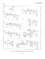
7-C-21. The Ohms Current Source consists of a Voltage
Reference, Buffer and Range Resistors, and a Gate Bias
Amplifier. Before troubleshooting the current source,
make sure the + 10V reference is good at JM201. To
troubleshoot the Ohms Current Source, do the following
procedure.
a. Set the 3478A to the 2-Wire Ohms Function and
the 3K ohm Range.
b. Using a high impedance Digital Voltmeter (like
the 3456A), measure the voltage at pin 2 and pin 3 of
U203 (U102 pins 17 and 18, respectively). Make sure
the voltage on both pins is approxi8V.
c. If the voltages are not approximately the same,
replace U203.
d. If the voltages on both pins are wrong (other than
+8V), but are approximately the same, do the following:
1. Measure for approxi 12V at pin 6 of
U201.
2. If the voltage at pin 6 of U201 is + 12V,
replace U102. Before replacing U102, make sure
the A/D Controller (U462) is good. Go to paragraph
7-C-24 to check U462.
3. If the voltage at pin 6 of U201 is other than
+12V, measure for approxi8V at pin 3 of
U201.
4. If the voltage at pin 3 of U201 is wrong,
replace U102. Before replacing U102, make sure
7-C-3
Summary of Contents for 3478A
Page 2: ...TM 11 6625 3071 14 A ...
Page 4: ...TM 11 6625 3071 14 C D BLANK ...
Page 12: ...TM 11 6625 3071 14 Table 1 1 Specification 1 2 ...
Page 13: ...TM 11 6625 3071 14 Table 1 1 Specifications Cont 1 3 ...
Page 14: ...TM 11 6625 3071 14 Table 1 1 Specifications Cont 1 4 ...
Page 53: ...TM 11 6625 3071 14 1 ...
Page 54: ...TM 11 6625 3071 14 2 ...
Page 55: ...TM 11 6625 3071 14 3 ...
Page 56: ...TM 11 6625 3071 14 4 ...
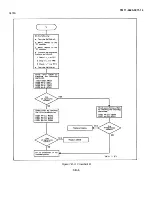
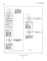
Page 87: ...TM 11 6625 3071 14 3478A Figure 7 D 3 Flowchart B 7 D 5 ...
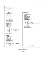
Page 88: ...TM 11 6625 3071 14 3478A Figure 7 D 4 Flowchart C 7 D 6 ...
Page 91: ...TM 11 6625 3071 14 3478A Figure 7 D 6 Flowchart D 7 D 9 ...
Page 111: ...TM 11 6625 3071 14 Figure 7 F 17 3478A Simplified Reference Circuitry 7 F 16 ...
Page 122: ...TM 11 6625 3071 14 Table A 2 A 2 HP IB Worksheet A 4 ...
Page 137: ...TM 11 6625 3071 14 Figure 7 D 2 Flow chart A 7 D 3 ...
Page 139: ...TM 11 6625 3071 14 Figure 7 G 2 3478A Block Diagram 7 G 3 ...
Page 140: ...TM 11 6625 3071 14 Component Locator for Input Circuitry and Ohms Current Source 7 G 4 ...
Page 141: ...TM 11 6625 3071 14 Figure 7 G 3 Input Circuitry and Ohms Current Source 7 G 5 ...
Page 142: ...TM 11 6625 3071 14 F G 6 ...
Page 143: ...TM 11 6625 3071 14 2 Figure 7 G 4 AC to DC Converter 7 G 7 ...
Page 144: ...TM 11 6625 3071 14 Component Locator for A D Converter and Control Logic 7 G 8 ...
Page 145: ...TM 11 6625 3071 14 3 Figure 7 G 5 A D Converter and Control Logic 7 G 9 ...
Page 146: ...TM 11 6625 3071 14 7 G 10 ...
Page 147: ...TM 11 6625 3071 14 4 Figure 7 G 6 Power Supplies 7 G 11 7 G 12 blank ...
Page 148: ......
Page 149: ...PIN NO 057444 ...

