TM 11-6625-3071-14
3478A
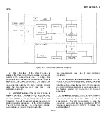
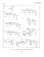
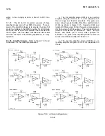
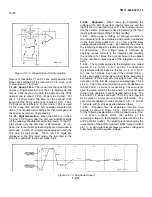
d. Ohms Low Sense Path (Figure 7-F-2E). This
path consists of RI01, R102, and S6ADC and S6CDC
(S6ADC and S6CDC are in U102). The path is used to
connect the LO OHMS SENSE Input Terminal (low ohms
input) to ground (LO INPUT Terminal), when the 3478A
is in the 4-Wire Ohms Function. In the 2-Wire Ohms
Function, the low ohms input is the LO INPUT Terminal
(which is connected to ground).
e.
Current Input Path (Figure 7-F-2F). This path
in- cludes R107 and S3DC (in U102). The voltage drop
across R107 (which is generated by the current being
measured) is connected through S3DC to the DC/Ohms
Input Amplifier. This path is used only in the DC Cur-
rent Function.
7-F-14. Autozero. The Autozero Function of the 3478A
is used to measure the offset (called a zero measure-
ment) of the DC/Ohms Input Amplifier and subtract it
from the input measurement. As long as the Autozero
Function is enabled, a zero measurement is taken be-
tween each input measurement. The zero measurement
is done in two different ways, dependent on the function
selected. The following explains the two ways to make
the measurement and the circuitry used.
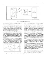
a.
Autozero (in the DC Volts, DC Current, and 2-
Wire Ohms Functions). In the DC Volts, DC Current,
and 2-Wire Ohms Functions, the zero measurement is
made with switch MC (measure customer) open, and
switch MZ (measure zero) and S8DC closed (see Figure
7-F-2G). Switch SSDC and MZ connects the DC/Ohms
Input Amplifier to ground through a 102K ohm resistor.
After the zero measurement is made, switch S8DC and
MZ opens, and switch MC closes for the input measure-
ment. (Note: MOSFET switches MC, MZ, and S8DC are
in U102.)
b. Autozero (in the 4-Wire Ohms Function). In
the 4-Wire Ohms Function, the zero measurement is
made with switch MC (and S8DC) open and switch MZ,
S6ADC, and S6BDC closed. The DC/Ohms Input
Amplifier is connected to ground through the Ohms Low
Sense Path (includes an externally connected lead; see
Figure 7-F-2H) to the LO INPUT Terminal. This
measurement is different than in the DC Volts, DC Cur-
rent, and 2-Wire Ohms Functions, since the Input
Amplifier is connected to ground through the externally
connected low ohms sense and lo input leads. After the
offset measurement is made, switch MC and S6CDC
closes and switch MZ, S6ADC, and S6BDC opens.
Switch S6CDC is used to to connect the junction of
switch S6ADC and S6BDC to ground, shunting any
possible voltage on the junction to ground. (Note:
MOSFET switches S6ADC, S6BDC, and S6CDC are in
U102.)
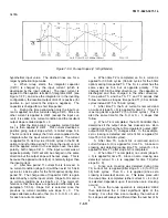
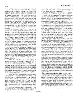
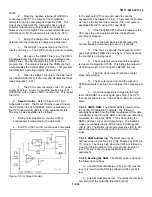
7-F-15. Pre-Charge Stage (Figure 7-F-21). A small
stray capacitance exists in U102 between the input of the
DC/Ohms Input Amplifier and ground. During a zero
measurement (measure zero in the Autozero Function),
this capacitor is at zero volts. After the zero measure-
ment, the input to the 3478A is applied to the Input
Amplifier and the capacitor is charged to the input
voltage. This charging may temporarily load down the
input voltage and a wrong reading is taken. To prevent
this, the input of the Input Amplifier is pre-charged to the
input voltage before the input measurement is made.
This is done by the Pre-Charge Amp and MOSFET
Switch PRE (both in U102). The operation is as follows:
a.
After the zero measurement is made, switch
PRE closes (switch MC is still open).
b.
The input voltage is connected to the Pre-
Charge Amp using the input paths.
c.
Since the Pre-Charge Amp is a XI gain amplifier,
a voltage with the same polarity and value as the input
voltage is applied through PRE to the DC/Ohms Input
Amplifier. This pre-charges the stray capacitor to the in-
put voltage.
d.
Switch PRE then opens and MC closes. An
input measurement is then made.
e.
The same takes place before the next zero
measure- ment.
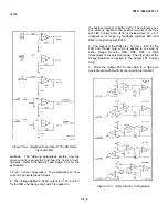
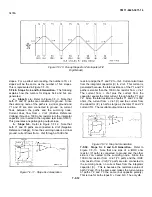
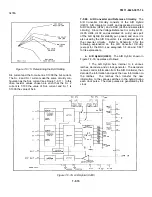
7-F-16. DC/Ohms Input Amplifier. The purpose of the
DC/Ohms Input amplifier, in conjunction with the In- put
Switching Circuitry, is to condition the 3478A’s in- put
signals. The conditioning is done to apply the same full
scale IOV dc voltage to the A/D Converter for all DC
Volts, DC Current, and Ohms full scale inputs. This is
done by configuring the amplifier to a gain of X3.33,
X33.3, or X333. The gains used in the 3478A’s different
ranges (in the DC Volts, DC Current, and Ohms Func-
tions) is shown in Figure 7-F-3.
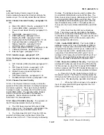
7-F-17. Ohms Current Source
7-F-18. General. The purpose of the Ohms Current
Source is to provide a stable current for resistance
measurements. The current is applied to the unknown
resistance and the resultant voltage drop across the
resistance is measured. Since this voltage drop is
directly proportional to the unknown resistance, the
resistance value is determined by the 3478A’s Main
Controller from the voltage reading.
7-F-19. The Ohms Current Source consists of the
following circuitry: Voltage Splitter (Voltage Reference),
Buffer, Range Resistors, Output FET Control Amp (Gate
Bias Amplifier), Output MOSFET, and Overvoltage
Protection. In addition to these, a number of MOSFETS
are used as switches (to select various gain determining
resistors). All the previously mentioned FETs are inside
U102 which also controls the FET
7-F-5
Summary of Contents for 3478A
Page 2: ...TM 11 6625 3071 14 A ...
Page 4: ...TM 11 6625 3071 14 C D BLANK ...
Page 12: ...TM 11 6625 3071 14 Table 1 1 Specification 1 2 ...
Page 13: ...TM 11 6625 3071 14 Table 1 1 Specifications Cont 1 3 ...
Page 14: ...TM 11 6625 3071 14 Table 1 1 Specifications Cont 1 4 ...
Page 53: ...TM 11 6625 3071 14 1 ...
Page 54: ...TM 11 6625 3071 14 2 ...
Page 55: ...TM 11 6625 3071 14 3 ...
Page 56: ...TM 11 6625 3071 14 4 ...
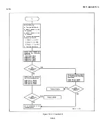
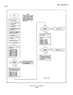
Page 87: ...TM 11 6625 3071 14 3478A Figure 7 D 3 Flowchart B 7 D 5 ...
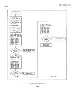
Page 88: ...TM 11 6625 3071 14 3478A Figure 7 D 4 Flowchart C 7 D 6 ...
Page 91: ...TM 11 6625 3071 14 3478A Figure 7 D 6 Flowchart D 7 D 9 ...
Page 111: ...TM 11 6625 3071 14 Figure 7 F 17 3478A Simplified Reference Circuitry 7 F 16 ...
Page 122: ...TM 11 6625 3071 14 Table A 2 A 2 HP IB Worksheet A 4 ...
Page 137: ...TM 11 6625 3071 14 Figure 7 D 2 Flow chart A 7 D 3 ...
Page 139: ...TM 11 6625 3071 14 Figure 7 G 2 3478A Block Diagram 7 G 3 ...
Page 140: ...TM 11 6625 3071 14 Component Locator for Input Circuitry and Ohms Current Source 7 G 4 ...
Page 141: ...TM 11 6625 3071 14 Figure 7 G 3 Input Circuitry and Ohms Current Source 7 G 5 ...
Page 142: ...TM 11 6625 3071 14 F G 6 ...
Page 143: ...TM 11 6625 3071 14 2 Figure 7 G 4 AC to DC Converter 7 G 7 ...
Page 144: ...TM 11 6625 3071 14 Component Locator for A D Converter and Control Logic 7 G 8 ...
Page 145: ...TM 11 6625 3071 14 3 Figure 7 G 5 A D Converter and Control Logic 7 G 9 ...
Page 146: ...TM 11 6625 3071 14 7 G 10 ...
Page 147: ...TM 11 6625 3071 14 4 Figure 7 G 6 Power Supplies 7 G 11 7 G 12 blank ...
Page 148: ......
Page 149: ...PIN NO 057444 ...


