
EL-MF877-00 Page 2
Template Revision B
PSG instructions for this template are available at
Components, parts and materials containing
refractory ceramic fibers
0
Components, parts and materials containing
radioactive substances
0
2.0 Tools Required
List the type and size of the tools that would typically be used to disassemble the product to a point where components
and materials requiring selective treatment can be removed.
Tool Description
Tool Size (if
applicable)
Torx Driver
T6/T10/T15
Phillips Driver
#0,#1, #2
Diagonal cutter
medium size
Pry Bar
Small
3.0 Product Disassembly Process
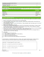
3.1 List the basic steps that should typically be followed to remove components and materials requiring selective treatment:
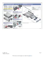
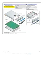
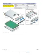
1. Remove unit from System rack by removing Torx T15 mounting screws
2. Pull release handles on Drives sleds to remove Hard drives / SSD modules; separate plastics and hard drives from
frame using phillps screw driver.
3. Pull release handle on Node(s) to remove from Drive bay. Remove heat pipe and/or heat sinks using T10 Torx driver;
Remove PCBA from Frame.
4. Remove coin cell battery from node board.
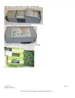
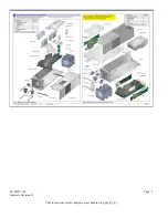
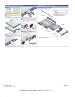
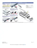
5. Remove Power Cooling Modules by depressing on the latch, the unit will slide out of the drive bay. Remove Lithium
Ion battery pack.(see step 6) Uses Phillips #1 to remove screws on the enclosure, remove PCBAs from housing,
remove electrolytic capacitors 1 4cm high; 10, 2.4 cm 10, 1cm.
6. Remove cover of lithium ion battery pack, using phillips #1, remove battery pack from enclosure; do not short batteries!
Carefully remove Lithium ion batteries by severing the metal tabs with a diagonal cutter.
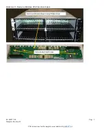
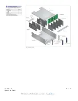
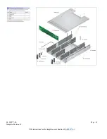
7. Using phillips #1 Screw driver remove plastic sections from the drive bay; Then remove the mid-plane PCBA; this
board has several 1cm electrolytic capacitors.
8.
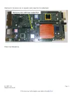
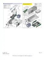
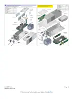
9. Node Steps:
10. 2. Remove top cover from array node.
11. 3. Remove DIMM's, and BOOT drive from node assembly.
12. 4. Use pry bar to remove capacitors.
13. 5. Remove coin battery from motherboard.
14. 6. Remove torx screws which attach motherboard to the sheetmetal.
15.
3.2 Optional Graphic. If the disassembly process is complex, insert a graphic illustration below to identify the items
contained in the product that require selective treatment (with descriptions and arrows identifying locations).
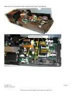
Attachment 1 – removing midplane PCA from drive chassis
Attachment 2—removing battery pack from Power Cooling Module
Attachment 3—removing electrolytic caps from Power Cooling Module
Attachment 4—removing coin cell from Node PCA


