Removal and replacement procedures 92
3.
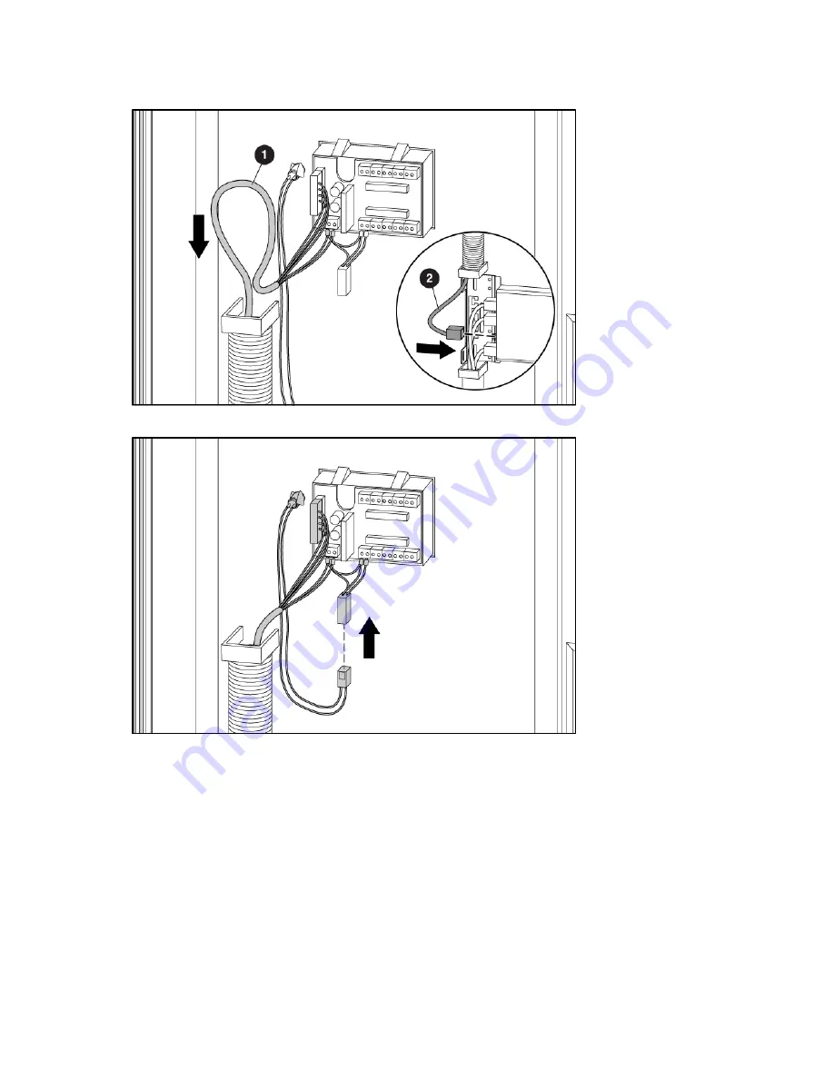
Push the cable down through the cable management hose (1), and connect it to the management
module connector (2).
4.
Connect the connector between the operator display and display button.
5.
Slide any extra slack in the cable lines up into the operator display rear cover, and secure by
inserting the rubber grommet into the designated notch on the operator display rear cover.
Summary of Contents for 403349-003
Page 13: ...Customer self repair 13 ...
Page 14: ...Customer self repair 14 ...
Page 15: ...Customer self repair 15 ...
Page 16: ...Customer self repair 16 ...


