5.
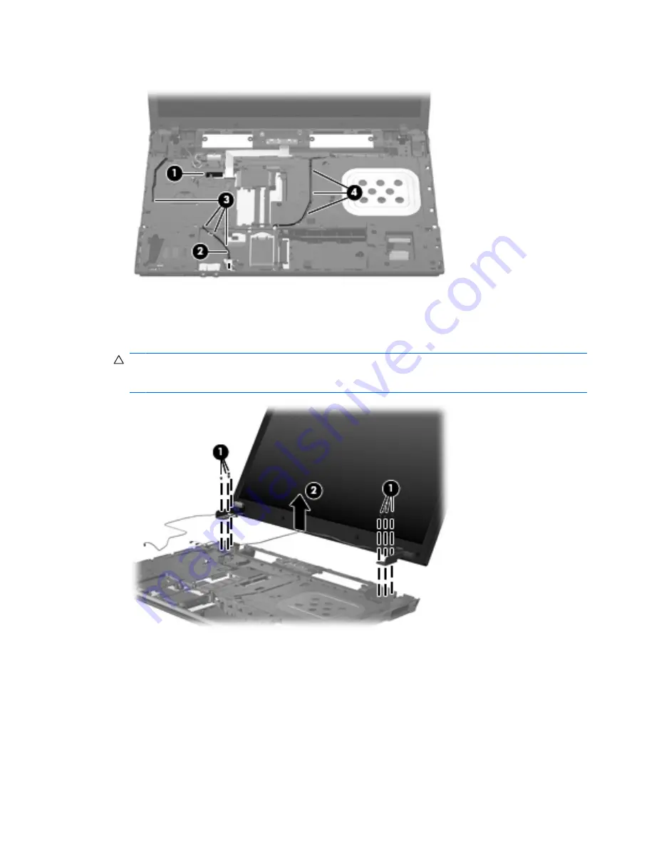
Remove the wireless antenna cables
(4)
from the clips and routing channels built into the top cover.
Remove the display assembly:
1.
Remove the six Phillips PM2.5×4.5 screws
(1)
that secure the display assembly to the computer,
and then lift the display assembly straight up
(2)
and remove it.
CAUTION:
Support the display assembly when removing the following screws. Failure to support
the display assembly can result in damage to the display assembly and other computer
components.
60
Chapter 4 Removal and replacement procedures
Summary of Contents for 4710s - ProBook - Core 2 Duo 2.53 GHz
Page 1: ...HP ProBook 4710s Notebook PC Maintenance and Service Guide ...
Page 4: ...iv MSG revision history ...
Page 6: ...vi Safety warning notice ...
Page 123: ...Where used 1 screw that secures the USB board to the computer Phillips PM2 5 3 0 screw 113 ...
Page 151: ...22 Remove the LCD panel 23 Recycle the LCD panel and backlight Display 141 ...
Page 157: ......


