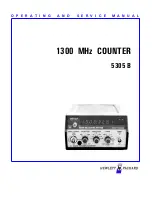
Model 5305B
Operation
SECTION IX E
5305B 1300 MHz COUNTER
SUBSECTION III
OPERATION
9E-3-8. The frequency range of Channel B depends on the
mode of operation - normal or high resolution. In the
normal mode, Channel B covers 50 Hz to 100 MHz. With
high-resolution selected, Channel B covers 50 Hz to 10
kHz. The high resolution mode uses a phase-locked
multiplier to increase resolution by a factor of 1000. Input
impedance is 1 Megohm shunted by less than 40 pF. A 10
to 1 divider probe can be used to increase the input
impedance to 10 Megohms.
9E-3-1. INTRODUCTION
9E-3-2. This section covers operating information for the
5305B including a description of controls, indicators, and
connectors, resolution, input levels, and operating
procedures for frequency measurements and self check.
9E-3-3. OPERATING CHARACTERISTICS
9E-3-9. RESOLUTION
9E-3-4. The 5305B Counter performs frequency mea-
surements by means of two separate input channels. These
channels provide a combination of low frequency
measurements and high-sensitivity, high frequency
measurements. Measurement capability is applicable to all
frequencies in the VHF and mobile communication bands in
addition to a significant portion of the UHF band. The
10855A Preamplifier can be used to boost the UHF input
sensitivity by 22 dB.
9E-3-10. The 5305B has a RESOLUTION switch which
determines the least-significant digit (LSD) displayed. For
example, with an input of 123,456 Hz, setting the
RESOLUTION switch to 1 kHz places the "3" in the LSD.
Setting the switch to 10 Hz, places the "5" in the LSD.
Resolution can be expressed in terms of the counter's gate
time, as shown in Table 9E-3-1.
9E-3-5. Input channels
Table 9E-3-1. Resolution vs Gate time
Figure 9E-3-1. dBm-to-Voltage Conversions
9E-3-6. Two input channels are provided, Channel A - 90
MHz to 1300 MHz and Channel B - 50 Hz to 100 MHz.
Both channels have 20 mV rms sensitivity.
9E-3-7. Channel A prescales the input frequency by 16 and
can be used to measure CW or burst signals. Input coupling
is ac. An AGC circuit is included to give a dynamic range
of >47 dB. An internal fuse, located inside the input jack,
protects circuitry from overloads greater than 5V rms. Note
that a blown fuse may not prevent the counter from
measuring high-frequency inputs. In this instance, the
counter’s circuitry is no longer protected,ie.,as it would be
at lower frequencies by a good open circuit. If the fuse
blows, a replacement fuse is supplied with the instrument.
RESOLUTION GATE
TIME
80 MHz
1100 MHz
.1 Hz
10 s
160 s
1 Hz
1 s
16 s
10 Hz
.1 s
1.6 s
100Hz .01s .16s
1 kHz
1 ms
16 ms
10 kHz
.1 ms
1.6 ms
9E-3-1
Summary of Contents for 5305 B
Page 1: ...O P E R A T I N G A N D S E R V I C E M A N U A L 5305 B 1300 MHz COUNTER ...
Page 21: ...Model 5305B Maintenance STEP A STEP B 9E 5 2 Figure 9E 5 1 Separation Procedure ...
Page 43: ......
Page 47: ......
Page 48: ......


