background image


281 


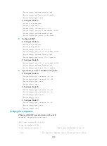
  9::2                 65009       41       43    0       1 00:29:00 Established 

  10::2                65008       38       38    0       2 00:27:20 Established 

The output shows that Router A and Router B have established an EBGP connection, and Router B and 
Router C have established an IBGP connection. 
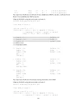
# Display IPv6 BGP routing table information on Router A.  

[RouterA] display bgp routing-table ipv6 


 Total number of routes: 4 


 BGP local router ID is 1.1.1.1 

 Status codes: * - valid, > - best, d - dampened, h - history, 

               s - suppressed, S - stale, i - internal, e - external 

               Origin: i - IGP, e - EGP, ? - incomplete 


* >e Network : 9::                                      PrefixLen : 64 

     NextHop : 10::1                                    LocPrf    : 

     PrefVal : 0                                        OutLabel  : NULL 

     MED     : 0 

     Path/Ogn: 65009i 


* >  Network : 10::                                     PrefixLen : 64 

     NextHop : ::                                       LocPrf    : 

     PrefVal : 32768                                    OutLabel  : NULL 

     MED     : 0 

     Path/Ogn: i 


*  e Network : 10::                                     PrefixLen : 64 

     NextHop : 10::1                                    LocPrf    : 

     PrefVal : 0                                        OutLabel  : NULL 

     MED     : 0 

     Path/Ogn: 65009i 


* >  Network : 50::                                     PrefixLen : 64 

     NextHop : ::                                       LocPrf    : 

     PrefVal : 32768                                    OutLabel  : NULL 

     MED     : 0 

     Path/Ogn: i 

The output shows that Router A has learned routing information of AS 65009.  
# Display IPv6 BGP routing table information on Router C.  

[RouterC] display bgp routing-table ipv6 


 Total number of routes: 4 


 BGP local router ID is 3.3.3.3 

 Status codes: * - valid, > - best, d - dampened, h - history, 

               s - suppressed, S - stale, i - internal, e - external 

Summary of Contents for 5500 EI series

Page 1: ...HP MSR2000 3000 4000 Router Series Layer 3 IP Routing Configuration Guide V7 Part number 5998 3992 Software version CMW710 R0007P02 Document version 6PW100 20130927 ...

Page 2: ...MATERIAL INCLUDING BUT NOT LIMITED TO THE IMPLIED WARRANTIES OF MERCHANTABILITY AND FITNESS FOR A PARTICULAR PURPOSE Hewlett Packard shall not be liable for errors contained herein or for incidental or consequential damages in connection with the furnishing performance or use of this material The only warranties for HP products and services are set forth in the express warranty statements accompan...

Page 3: ...ion examples 11 Basic static route configuration example 11 BFD for static routes configuration example direct next hop 13 BFD for static routes configuration example indirect next hop 16 Static route FRR configuration example 18 Configuring a default route 20 Configuring RIP 21 Overview 21 RIP route entries 21 Routing loop prevention 21 RIP operation 21 RIP versions 22 Protocols and standards 22 ...

Page 4: ...P route redistribution 40 Configuring an additional metric for a RIP interface 42 Configuring RIP to advertise a summary route 44 Configuring BFD for RIP single hop echo detection for a directly connected neighbor 46 Configure BFD for RIP single hop echo detection for a specific destination 49 Configuring BFD for RIP bidirectional control detection 51 Configuring RIP FRR 55 Configuring OSPF 58 Ove...

Page 5: ...Configuring OSPF exit overflow interval 84 Enabling compatibility with RFC 1583 84 Logging neighbor state changes 85 Configuring OSPF network management 85 Configuring the LSU transmit rate 86 Enabling OSPF ISPF 86 Configuring prefix suppression 87 Configuring prefix suppression for an OSPF process 87 Configuring prefix suppression on an interface 87 Configuring prefix prioritization 88 Configurin...

Page 6: ...tion 134 Advertising a default route 134 Configuring IS IS route redistribution 135 Configuring IS IS route filtering 135 Configuring IS IS route leaking 136 Tuning and optimizing IS IS networks 137 Configuration prerequisites 137 Specifying the interval for sending IS IS hello packets 137 Specifying the IS IS hello multiplier 137 Specifying the interval for sending IS IS CSNP packets 138 Configur...

Page 7: ...large scale BGP networks 180 MP BGP 183 BGP configuration views 184 Protocols and standards 185 BGP configuration task list 186 Configuring basic BGP 188 Enabling BGP 188 Configuring a BGP peer 189 Configuring a BGP peer group 190 Specifying the source interface for TCP connections 196 Generating BGP routes 197 Injecting a local network 197 Redistributing IGP routes 198 Controlling route distribut...

Page 8: ...lities 244 Displaying and maintaining BGP 245 IPv4 BGP configuration examples 248 Basic BGP configuration example 248 BGP and IGP route redistribution configuration example 252 BGP route summarization configuration example 255 BGP load balancing configuration example 258 BGP community configuration example 261 BGP route reflector configuration example 264 BGP confederation configuration example 26...

Page 9: ...dards 323 RIPng configuration task list 323 Configuring basic RIPng 323 Configuring RIPng route control 324 Configuring an additional routing metric 324 Configuring RIPng route summarization 324 Advertising a default route 325 Configuring received redistributed route filtering 325 Configuring a preference for RIPng 326 Configuring RIPng route redistribution 326 Tuning and optimizing the RIPng netw...

Page 10: ...rface 348 Ignoring MTU check for DD packets 349 Disabling interfaces from receiving and sending OSPFv3 packets 349 Enabling the logging of neighbor state changes 349 Configuring OSPFv3 GR 350 Configuring GR restarter 350 Configuring GR helper 350 Configuring BFD for OSPFv3 351 Applying an IPsec profile 351 Displaying and maintaining OSPFv3 353 OSPFv3 configuration examples 353 Configuring OSPFv3 a...

Page 11: ...6 Overview 396 Filters 396 Routing policy 397 Configuring filters 397 Configuration prerequisites 397 Configuring an IP prefix list 398 Configuring an AS path list 398 Configuring a community list 398 Configuring an extended community list 399 Configuring a MAC list 399 Configuring a routing policy 399 Configuration prerequisites 399 Creating a routing policy 400 Configuring if match clauses 400 C...

Page 12: ...t mask is 32 bits Whether the destination is directly connected Direct route The destination is directly connected Indirect route The destination is indirectly connected Origin Direct route A direct route is discovered by the data link protocol on an interface and is also called an interface route Static route A static route is manually configured by an administrator Dynamic route A dynamic route ...

Page 13: ...de RIP OSPF and IS IS EGPs Work between ASs The most popular EGP is BGP Routing algorithm Distance vector protocols Examples include RIP and BGP BGP is also considered a path vector protocol Link state protocols Examples include OSPF and IS IS Destination address type Unicast routing protocols Examples include RIP OSPF BGP and IS IS Multicast routing protocols Examples include PIM SM and PIM DM IP...

Page 14: ...he highest priority is the primary route and others are secondary routes The router forwards matching packets through the primary route When the primary route fails the route with the highest preference among the secondary routes is selected to forward packets When the primary route recovers the router uses it to forward packets Route recursion To use a BGP static or RIP route that has an indirect...

Page 15: ...rotocol convergence resulting from a large number of route entries or long GR period The configuration takes effect at the next protocol or RIB process switchover To configure the maximum lifetime for routes and labels in the RIB IPv4 Step Command Remarks 1 Enter system view system view N A 2 Enter RIB view rib N A 3 Create a RIB IPv4 address family and enter RIB IPv4 address family view address f...

Page 16: ...is 600 seconds To configure the maximum lifetime for routes in the FIB IPv6 Step Command Remarks 1 Enter system view system view N A 2 Enter RIB view rib N A 3 Create a RIB IPv6 address family and enter its view address family ipv6 By default no RIB IPv6 address family is created 4 Configure the maximum lifetime for IPv6 routes in the FIB fib lifetime seconds By default the maximum lifetime for ro...

Page 17: ...to an IPv6 destination address display ipv6 routing table vpn instance vpn instance name ipv6 address prefix length longer match verbose Display information about routes permitted by an IPv6 basic ACL display ipv6 routing table vpn instance vpn instance name acl acl6 number verbose Display information about routes to a range of IPv6 destination addresses display ipv6 routing table vpn instance vpn...

Page 18: ... Guide To configure a static route Step Command Remarks 1 Enter system view system view N A 2 Configure a static route Method 1 ip route static dest address mask mask length next hop address track track entry number interface type interface number next hop address vpn instance d vpn instance name next hop address track track entry number permanent preference preference value tag tag value descript...

Page 19: ...peer To configure a static route and enable BFD control mode for it specify an output interface and a direct next hop or specify an indirect next hop and a specific BFD packet source address for the static route To configure BFD control mode for a static route direct next hop Step Command Remarks 1 Enter system view system view N A 2 Configure BFD control mode for a static route Method 1 ip route ...

Page 20: ...ackets to the destination device which loops the packets back to test the link reachability IMPORTANT Do not use BFD for a static route with the output interface in spoofing state To configure BFD echo mode for a static route Step Command Remarks 1 Enter system view system view N A 2 Configure the source address of echo packets bfd echo source ip ip address By default the source address of echo pa...

Page 21: ...ut interface is unavailable Equal cost routes do not support static route FRR The backup output interface and next hop cannot be modified directly or the same as the primary output interface and next hop Static route FRR is available only when the state of primary link with Layer 3 interfaces staying up changes from bidirectional to unidirectional or down A unidirectional link refers to the link t...

Page 22: ...address permanent Use either method By default static route FRR is not configured Displaying and maintaining static routes Execute display commands in any view Task Command Display static route information display ip routing table protocol static inactive verbose Display static route next hop information display route static nib nib id verbose Display static routing table information display route...

Page 23: ... Configure a default route on Router C RouterC system view RouterC ip route static 0 0 0 0 0 0 0 0 1 1 5 5 3 Configure the default gateways of Host A Host B and Host C as 1 1 2 3 1 1 6 1 and 1 1 3 1 Details not shown Verifying the configuration Display the static route information on Router A RouterA display ip routing table protocol static Summary Count 1 Static Routing table Status Active Summar...

Page 24: ...0 loss Approximate round trip times in milli seconds Minimum 1ms Maximum 1ms Average 1ms Use the tracert command on Host B to test the reachability of Host A C Documents and Settings Administrator tracert 1 1 2 2 Tracing route to 1 1 2 2 over a maximum of 30 hops 1 1 ms 1 ms 1 ms 1 1 6 1 2 1 ms 1 ms 1 ms 1 1 4 1 3 1 ms 1 ms 1 ms 1 1 2 2 Trace complete BFD for static routes configuration example di...

Page 25: ...ic 120 1 1 0 24 ethernet 1 1 12 1 1 2 bfd control packet RouterA ip route static 120 1 1 0 24 ethernet 1 2 10 1 1 100 preference 65 RouterA quit Configure static routes on Router B and enable BFD control mode for the static route that traverses the Layer 2 switch RouterB system view RouterB interface ethernet 1 1 RouterB Ethernet1 1 bfd min transmit interval 500 RouterB Ethernet1 1 bfd min receive...

Page 26: ...ctive Summary Count 1 Destination Mask Proto Pre Cost NextHop Interface 120 1 1 0 24 Static 60 0 12 1 1 2 Eth1 1 Static Routing table Status Inactive Summary Count 0 The output shows that Router A communicates with Router B through Ethernet 1 1 Then the link over Ethernet 1 1 fails Display static routes on Router A RouterA display ip routing table protocol static Summary Count 1 Static Routing tab...

Page 27: ...ice Interface IP address Device Interface IP address Router A Eth1 1 12 1 1 1 24 Router B Eth1 1 11 1 1 2 24 Eth1 2 10 1 1 102 24 Eth1 2 13 1 1 2 24 Loop1 1 1 1 9 32 Loop1 2 2 2 9 32 Router C Eth1 1 10 1 1 100 24 Router D Eth1 1 12 1 1 2 24 Eth1 2 13 1 1 2 24 Eth1 2 11 1 1 2 24 Configuration procedure 1 Configure IP addresses for interfaces Details not shown 2 Configure static routes and BFD Confi...

Page 28: ... the BFD session information on Router A RouterA display bfd session Total Session Num 1 Up Session Num 1 Init Mode Active IPv4 Session Working Under Ctrl Mode LD RD SourceAddr DestAddr State Holdtime Interface 4 7 1 1 1 9 2 2 2 9 Up 2000ms N A The output shows that the BFD session has been created Display static routes on Router A RouterA display ip routing table protocol static Summary Count 1 S...

Page 29: ... route on Router S and specify Ethernet 1 1 as the backup output interface and 12 12 12 2 as the backup next hop RouterS system view RouterS bfd echo source ip 4 4 4 4 RouterS ip route static 4 4 4 4 32 ethernet 1 2 13 13 13 2 backup interface ethernet 1 1 backup nexthop 12 12 12 2 Configure a static route on Router D and specify Ethernet 1 1 as the backup output interface and 24 24 24 2 as the ba...

Page 30: ...terface Ethernet1 2 BkTunnel ID Invalid BkInterface Ethernet1 1 Display route 1 1 1 1 32 on Router D to view the backup next hop information RouterS display ip routing table 1 1 1 1 verbose Summary Count 1 Destination 1 1 1 1 32 Protocol Static Process ID 0 SubProtID 0x0 Age 04h20m37s Cost 0 Preference 10 Tag 0 State Active Adv OrigTblID 0x0 OrigVrf default vrf TableID 0x2 OrigAs 0 NBRID 0x2600000...

Page 31: ...following ways The network administrator can configure a default route with both destination and mask being 0 0 0 0 For more information see Configuring a static route Some dynamic routing protocols such as OSPF RIP and IS IS can generate a default route For example an upstream router running OSPF can generate a default route and advertise it to other routers which install the default route with t...

Page 32: ...st update The time is reset to 0 when the routing entry is updated Route tag Used for route control For more information see Configuring routing policies Routing loop prevention RIP uses the following mechanisms to prevent routing loops Counting to infinity A destination with a metric value of 16 is considered unreachable When a routing loop occurs the metric value of a route will increment to 16 ...

Page 33: ...uting policies Supports masks route summarization and CIDR Supports designated next hops to select the best ones on broadcast networks Supports multicasting route updates so only RIPv2 routers can receive these updates to reduce resource consumption Supports plain text authentication and MD5 authentication to enhance security RIPv2 supports two transmission modes broadcast and multicast Multicast ...

Page 34: ...GR Optional Configuring BFD for RIP Optional Configuring RIP FRR Configuring basic RIP Before you configure basic RIP settings complete the following tasks Configure the link layer protocol Configure IP addresses for interfaces to ensure IP connectivity between neighboring routers Enabling RIP To enable multiple RIP processes on a router you must specify an ID for each process A RIP process ID has...

Page 35: ... Enable RIP on the interface rip process id enable exclude subip By default RIP is disabled on an interface Controlling RIP reception and advertisement on interfaces Step Command Remarks 1 Enter system view system view N A 2 Enter RIP view rip process id vpn instance vpn instance name N A 3 Disable an interface from sending RIP messages silent interface interface type interface number all By defau...

Page 36: ... 5 Enter interface view interface interface type interface number N A 6 Specify a RIP version for the interface rip version 1 2 broadcast multicast By default no interface specific RIP version is specified and the interface sends RIPv1 broadcasts and can receive RIPv1 broadcasts and unicasts and RIPv2 broadcasts multicasts and unicasts Configuring RIP route control Before you configure RIP route c...

Page 37: ... 0 24 10 1 2 0 24 and 10 1 3 0 24 Automatic summarization automatically creates and advertises a summary route 10 0 0 0 8 instead of the more specific routes To enable RIPv2 automatic route summarization Step Command Remarks 1 Enter system view system view N A 2 Enter RIP view rip process id vpn instance vpn instance name N A 3 Optional Enable RIPv2 automatic route summarization summary By default...

Page 38: ...d vpn instance vpn instance name N A 3 Disable RIP from receiving host routes undo host route By default RIP receives host routes Advertising a default route You can advertise a default route on all RIP interfaces in RIP view or on a specific RIP interface in interface view The interface view setting takes precedence over the RIP view settings To disable an interface from advertising a default rou...

Page 39: ...prefix list name gateway prefix list name import interface type interface number By default the filtering of received routes is not configured This command filters received routes Filtered routes are not installed into the routing table or advertised to neighbors 4 Configure the filtering of redistributed routes filter policy acl number prefix list prefix list name export protocol process id inter...

Page 40: ...rotocol command 4 Optional Configure a default cost for redistributed routes default cost value The default setting is 0 Tuning and optimizing RIP networks Configuration prerequisites Before you tune and optimize RIP networks complete the following tasks Configure IP addresses for interfaces to ensure IP connectivity between neighboring nodes Configure basic RIP Configuring RIP timers You can chan...

Page 41: ... The timeout timer is 180 seconds The update timer is 30 seconds Configuring split horizon and poison reverse The split horizon and poison reverse functions can prevent routing loops If both split horizon and poison reverse are configured only the poison reverse function takes effect Enabling split horizon Split horizon disables RIP from sending routes through the interface where the routes were l...

Page 42: ...ntains a non zero value RIP does not process the message If you are certain that all messages are trustworthy disable zero field check to save CPU resources This feature does not apply to RIPv2 packets because they have no zero fields To enable zero field check on incoming RIPv1 messages Step Command Remarks 1 Enter system view system view N A 2 Enter RIP view rip process id vpn instance vpn insta...

Page 43: ...iew interface interface type interface number N A 3 Configure RIPv2 authentication rip authentication mode md5 rfc2082 cipher cipher string plain plain string key id rfc2453 cipher cipher string plain plain string simple cipher cipher string plain plain string By default RIPv2 authentication is not configured Specifying a RIP neighbor Typically RIP messages are sent in broadcast or multicast To en...

Page 44: ... packets and the maximum number of RIP packets that can be sent at each interval This feature can avoid excessive RIP packets from affecting system performance and consuming too much bandwidth To configure the RIP packet sending rate Step Command Remarks 1 Enter system view system view N A 2 Enter RIP view rip process id vpn instance vpn instance name N A 3 Specify the interval for sending RIP pac...

Page 45: ... It must have GR capability GR helper A neighbor of the GR restarter It helps the GR restarter to complete the GR process After RIP restarts on a router the router must learn RIP routes again and update its FIB table which causes network disconnections and route reconvergence With the GR feature the restarting router known as the GR restarter can notify the event to its GR capable neighbors GR cap...

Page 46: ...urce ip ip address By default the source IP address of BFD echo packets is not configured 3 Enter interface view interface interface type interface number N A 4 Enable BFD for RIP rip bfd enable By default BFD for RIP is disabled Configuring single hop echo detection for a specific destination When a unidirectional link occurs between the local device and a specific neighbor BFD can detect the fai...

Page 47: ...n routing loop until RIP completes routing convergence based on the new network topology FRR enables fast rerouting to minimize the impact of link or node failures Figure 6 Network diagram for RIP FRR In Figure 6 configure FRR on Router B by using a routing policy to specify a backup next hop When the primary link fails RIP directs packets to the backup next hop At the same time RIP calculates the...

Page 48: ...IP Execute display commands in any view and execute reset commands in user view Task Command Display RIP current status and configuration information display rip process id Display active routes in RIP database display rip process id database ip address mask mask length Display RIP interface information display rip process id interface interface type interface number Display routing information ab...

Page 49: ...ce ethernet 1 1 RouteB Ethernet1 1 rip 1 enable RouterB rip 1 quit RouterB interface ethernet 1 2 RouteB Ethernet1 2 rip 1 enable RouterB rip 1 quit RouterB interface ethernet 1 3 RouteB Ethernet1 3 rip 1 enable RouterB rip 1 quit Display the RIP routing table on Router A RouterA display rip 1 route Route Flags R RIP A Aging S Suppressed G Garbage collect O Optimal F Flush to RIB Peer 1 1 1 2 on E...

Page 50: ... Router B RouterB display rip 1 route Route Flags R RIP A Aging S Suppressed G Garbage collect O Optimal F Flush to RIB Peer 1 1 1 1 on Ethernet1 1 Destination Mask Nexthop Cost Tag Flags Sec 2 1 1 0 24 1 1 1 1 1 0 RAOF 19 3 1 1 0 24 1 1 1 1 1 0 RAOF 19 4 Configure RIP route filtering Use IP prefix lists on Router B to filter received and redistributed routes RouterB ip prefix list aaa index 10 pe...

Page 51: ...ect routes and routes from RIP 100 on Router B so Router C can learn routes destined for 10 2 1 0 24 and 1 1 1 1 0 24 Router A cannot learn routes destined for 12 3 1 0 24 and 16 4 1 0 24 Figure 8 Network diagram Configuration procedure 1 Configure IP addresses for interfaces Details not shown 2 Configure basic RIP Enable RIP 100 and configure RIPv2 on Router A RouterA system view RouterA rip 100 ...

Page 52: ...ect 0 0 127 0 0 1 InLoop0 12 3 1 255 32 Direct 0 0 12 3 1 2 Eth1 1 16 4 1 0 24 Direct 0 0 16 4 1 1 Eth1 2 16 4 1 0 32 Direct 0 0 16 4 1 1 Eth1 2 16 4 1 1 32 Direct 0 0 127 0 0 1 InLoop0 16 4 1 255 32 Direct 0 0 16 4 1 1 Eth1 2 127 0 0 0 8 Direct 0 0 127 0 0 1 InLoop0 127 0 0 0 32 Direct 0 0 127 0 0 1 InLoop0 127 0 0 1 32 Direct 0 0 127 0 0 1 InLoop0 127 255 255 255 32 Direct 0 0 127 0 0 1 InLoop0 ...

Page 53: ...Loop0 Configuring an additional metric for a RIP interface Network requirements As shown in Figure 9 run RIPv2 on all the interfaces of Router A Router B Router C Router D and Router E Router A has two links to Router D The link from Router B to Router D is more stable than that from Router C to Router D Configure an additional metric for RIP routes received from Ethernet 1 2 on Router A so Router...

Page 54: ...ost 1 nexthop 1 1 1 2 1 1 4 0 24 cost 1 nexthop 1 1 2 2 1 1 5 0 24 cost 2 nexthop 1 1 1 2 1 1 5 0 24 cost 2 nexthop 1 1 2 2 The output shows two RIP routes destined for network 1 1 5 0 24 with the next hops as Router B 1 1 1 2 and Router C 1 1 2 2 and with the same cost of 2 3 Configure an additional metric for a RIP interface Configure an additional metric of 3 for RIP enabled interface Ethernet ...

Page 55: ...tem view RouterA ospf RouterA ospf 1 area 0 RouterA ospf 1 area 0 0 0 0 network 10 5 1 0 0 0 0 255 RouterA ospf 1 area 0 0 0 0 network 10 2 1 0 0 0 0 255 RouterA ospf 1 area 0 0 0 0 quit Configure Router B RouterB system view RouterB ospf RouterB ospf 1 area 0 RouterB ospf 1 area 0 0 0 0 network 10 1 1 0 0 0 0 255 RouterB ospf 1 area 0 0 0 0 network 10 6 1 0 0 0 0 255 RouterB ospf 1 area 0 0 0 0 q...

Page 56: ...nLoop0 10 1 1 0 24 RIP 100 1 11 3 1 1 Eth1 1 10 2 1 0 24 RIP 100 1 11 3 1 1 Eth1 1 10 5 1 0 24 RIP 100 1 11 3 1 1 Eth1 1 10 6 1 0 24 RIP 100 1 11 3 1 1 Eth1 1 11 3 1 0 24 Direct 0 0 11 3 1 2 Eth1 1 11 3 1 0 32 Direct 0 0 11 3 1 2 Eth1 1 11 3 1 2 32 Direct 0 0 127 0 0 1 InLoop0 11 4 1 0 24 Direct 0 0 11 4 1 2 Eth1 2 11 4 1 0 32 Direct 0 0 11 4 1 2 Eth1 2 11 4 1 2 32 Direct 0 0 127 0 0 1 InLoop0 127...

Page 57: ... Router A and Router C runs RIP process 1 Ethernet 1 2 of Router A runs RIP process 2 Ethernet 1 2 of Router C and Ethernet 1 1 and Ethernet 1 2 of Router B run RIP process 1 Configure a static route destined for 100 1 1 1 24 and enable static route redistribution into RIP on Router C so Router A can learn two routes destined for 100 1 1 1 24 through Ethernet 1 1 and Ethernet 1 2 respectively and ...

Page 58: ...0 RouterC rip 1 network 192 168 3 0 RouterC rip 1 import route static RouterC rip 1 quit 2 Configure the BFD parameters on Ethernet 1 1 of Router A RouterA bfd session init mode active RouterA bfd echo source ip 11 11 11 11 RouterA interface ethernet 1 1 RouterA Ethernet1 1 bfd min transmit interval 500 RouterA Ethernet1 1 bfd min receive interval 500 RouterA Ethernet1 1 bfd detect multiplier 7 Ro...

Page 59: ... N A The output shows that Router A communicates with Router C through Ethernet 1 1 Then the link over Ethernet 1 1 fails Display RIP routes destined for 120 1 1 0 24 on Router A RouterA display ip routing table 120 1 1 0 24 verbose Summary Count 1 Destination 120 1 1 0 24 Protocol RIP Process ID 2 SubProtID 0x1 Age 04h20m37s Cost 1 Preference 100 Tag 0 State Active Adv OrigTblID 0x0 OrigVrf defau...

Page 60: ...ion When a unidirectional link occurs packets from Router A can reach Router B but packets from Router B cannot reach Router A BFD can quickly detect the link failure and notify RIP RIP then deletes the neighbor relationship and the route information learned on Ethernet 1 2 and does not receive or send any packets on Ethernet 1 2 When the route learned from Router A ages out Router B uses the rout...

Page 61: ...rC ip route static 100 1 1 0 24 null 0 Verifying the configuration Display the BFD session information on Router A RouterA display bfd session Total Session Num 1 Up Session Num 1 Init Mode Active IPv4 session working under Echo mode LD SourceAddr DestAddr State Holdtime Interface 3 192 168 2 1 192 168 2 2 Up 2000ms Eth1 2 Display routes destined for 100 1 1 0 24 on Router B RouterB display ip rou...

Page 62: ...tion Network requirements As shown in Figure 13 Ethernet 1 2 of Router A and Ethernet 1 1 of Router C run RIP process 1 Ethernet 1 1 on Router A runs RIP process 2 Ethernet 1 2 on Router C and Ethernet 1 1 and Ethernet 1 2 on Router D run RIP process 1 Configure a static route destined for 100 1 1 0 24 on Router A configure a static route destined for 101 1 1 0 24 on Router C and enable static rou...

Page 63: ... to each other Configure Router A RouterA system view RouterA rip 1 RouterA rip 1 version 2 RouterA rip 1 undo summary RouterA rip 1 network 192 168 1 0 RouterA rip 1 network 101 1 1 0 RouterA rip 1 peer 192 168 2 2 RouterA rip 1 undo validate source address RouterA rip 1 import route static RouterA rip 1 quit RouterA interface ethernet 1 2 RouterA Ethernet1 2 rip bfd enable RouterA Ethernet1 2 qu...

Page 64: ... RouterA interface ethernet 1 1 RouterA Ethernet1 1 ip address 192 168 3 1 24 RouterA Ethernet1 1 quit RouterA interface ethernet 1 2 RouterA Ethernet1 2 ip address 192 168 1 1 24 RouterA Ethernet1 2 bfd min transmit interval 500 RouterA Ethernet1 2 bfd min receive interval 500 RouterA Ethernet1 2 bfd detect multiplier 7 RouterA Ethernet1 2 quit Configure Router B RouterB system view RouterB inter...

Page 65: ...Display the BFD session information on Router A RouterA display bfd session Total Session Num 1 Up Session Num 1 Init Mode Active IPv4 session working under Ctrl mode LD RD SourceAddr DestAddr State Holdtime Interface 513 513 192 168 1 1 192 168 2 2 Up 1700ms Eth1 2 Display RIP routes destined for 100 1 1 0 24 learned on Router A RouterB display ip routing table 100 1 1 0 24 verbose Summary Count ...

Page 66: ...terface Ethernet1 2 BkTunnel ID Invalid BkInterface N A Configuring RIP FRR Network requirements As shown in Figure 14 Router S Router A and Router D run RIPv2 Configure RIP FRR so that when Link A becomes unidirectional traffic can be switched to Link B immediately Figure 14 Network diagram Configuration procedure 1 Configure IP addresses and subnet masks for interfaces on the routers Details not...

Page 67: ...ute route policy frr RouterD rip 1 quit Verifying the configuration Display route 4 4 4 4 32 on Router S to view the backup next hop information RouterS display ip routing table 4 4 4 4 verbose Destination 4 4 4 4 32 Protocol RIP Process ID 1 SubProtID 0x1 Age 04h20m37s Cost 1 Preference 100 Tag 0 State Active Adv OrigTblID 0x0 OrigVrf default vrf TableID 0x2 OrigAs 0 NBRID 0x26000002 LastAs 0 Att...

Page 68: ...s 0 NBRID 0x26000002 LastAs 0 AttrID 0xffffffff Neighbor 13 13 13 1 Flags 0x1008c OrigNextHop 13 13 13 1 Label NULL RealNextHop 13 13 13 1 BkLabel NULL BkNextHop 24 24 24 2 Tunnel ID Invalid Interface Ethernet1 2 BkTunnel ID Invalid BkInterface Ethernet1 1 ...

Page 69: ...ype 1 and external Type 2 routes Authentication Supports area and interface based packet authentication to ensure secure packet exchange Support for multicasting Multicasts protocol packets on some types of links to avoid impacting other devices OSPF packets OSPF messages are carried directly over IP The protocol number is 89 OSPF uses the following packet types Hello Periodically sent to find and...

Page 70: ...external LSA describes a route to another AS NSSA LSA Type 7 LSA as defined in RFC 1587 originated by ASBRs in NSSAs and flooded throughout a single NSSA NSSA LSAs describe routes to other ASs Opaque LSA A proposed type of LSA Its format consists of a standard LSA header and application specific information Opaque LSAs are used by the OSPF protocol or by some applications to distribute information...

Page 71: ...ks OSPF virtual links can solve this issue A virtual link is established between two ABRs through a non backbone area It must be configured on both ABRs to take effect The non backbone area is called a transit area In Figure 16 Area 2 has no direct physical link to the backbone Area 0 You can configure a virtual link between the two ABRs to connect Area 2 to the backbone area Figure 16 Virtual lin...

Page 72: ...a does no advertise inter area routes or external routes It advertises a default route in a Type 3 LSA so that the routers in the area can reach external networks through the default route NSSA area and totally NSSA area An NSSA area does not import AS external LSAs Type 5 LSAs but can import Type 7 LSAs generated by the NSSA ASBR The NSSA ABR translates Type 7 LSAs into Type 5 LSAs and advertises...

Page 73: ...o the following route levels Intra area route Inter area route Type 1 external route Type 2 external route The intra area and inter area routes describe the network topology of the AS The external routes describe routes to external ASs A Type 1 external route has high credibility The cost from a router to the destination of a Type 1 external route the cost from the router to the corresponding ASBR...

Page 74: ...nk layer protocol is Frame Relay ATM or X 25 OSPF considers the network type as NBMA by default OSPF packets are unicast on a NBMA network P2MP No link is P2MP type by default P2MP must be a conversion from other network types such as NBMA On a P2MP network OSPF packets are multicast to 224 0 0 5 P2P If the link layer protocol is PPP or HDLC OSPF considers the network type as P2P On a P2P network ...

Page 75: ...y synchronize their LSDBs through exchange of DD packets and LSAs DR and BDR election DR election is performed on broadcast or NBMA networks but not on P2P and P2MP networks Routers in a broadcast or NBMA network elect the DR and BDR by router priority and ID Routers with a router priority value higher than 0 are candidates for DR and BDR election The election votes are hello packets Each router s...

Page 76: ...ast network type for an interface Configuring the NBMA network type for an interface Configuring the P2MP network type for an interface Configuring the P2P network type for an interface Optional Configuring OSPF route control Configuring OSPF route summarization Configuring route summarization on an ABR Configuring route summarization when redistributing routes into OSPF on an ASBR Configuring rec...

Page 77: ...ent Configuring the LSU transmit rate Enabling OSPF ISPF Configuring prefix suppression Configuring prefix prioritization Configuring OSPF PIC Optional Configuring OSPF GR Configuring OSPF GR restarter Configuring OSPF GR helper Triggering OSPF GR Optional Configuring BFD for OSPF Optional Configuring OSPF FRR Enabling OSPF Enable OSPF before you perform other OSPF configuration tasks Configuratio...

Page 78: ...er ID is configured the highest loopback interface IP address if any is used as the router ID If no loopback interface IP address is available the highest physical interface IP address is used regardless of the interface status up or down 3 Enable an OSPF process and enter OSPF view ospf process id router id router id vpn instance vpn instance name By default OSPF is disabled 4 Optional Configure ...

Page 79: ...to the stub area so all packets destined outside of the AS are sent through the default route To further reduce the routing table size and routing information exchanged in the stub area configure a totally stub area by using the stub no summary command on the ABR AS external routes and inter area routes will not be distributed into the area All the packets destined outside of the AS or area will b...

Page 80: ... router id router id vpn instance vpn instance name N A 3 Enter area view area area id N A 4 Configure the area as an NSSA area nssa default route advertise cost cost nssa only route policy route policy name type type no import route no summary suppress fa translate always translate never translator stability interval value By default no area is configured as an NSSA area 5 Optional Specify a cost...

Page 81: ...default When you change the network type of an interface follow these guidelines When an NBMA network becomes fully meshed change the network type to broadcast to avoid manual configuration of neighbors If any routers in a broadcast network do not support multicasting change the network type to NBMA An NBMA network must be fully meshed OSPF requires that an NBMA network be fully meshed If a networ...

Page 82: ...r the interface as NBMA ospf network type nbma By default the network type of an interface depends on the link layer protocol 4 Optional Configure a router priority for the interface ospf dr priority priority The default setting is 1 The router priority configured with this command is for DR election 5 Return to system view quit N A 6 Enter OSPF view ospf process id router id router id vpn instanc...

Page 83: ...bor and its router priority peer ip address cost value dr priority dr priority By default no neighbor is specified This step must be performed if the network type is P2MP unicast and is optional if the network type is P2MP Configuring the P2P network type for an interface Step Command Remarks 1 Enter system view system view N A 2 Enter interface view interface interface type interface number N A 3...

Page 84: ... area area id N A 4 Configure ABR route summarization abr summary ip address mask mask length advertise not advertise cost cost By default no route summarization is configured The command takes effect only on an ABR Configuring route summarization when redistributing routes into OSPF on an ASBR Without route summarization an ASBR advertises each redistributed route in a separate ASE LSA After you ...

Page 85: ...ort By default OSPF accepts all routes calculated using received LSAs Configuring Type 3 LSA filtering Perform this task to filter Type 3 LSAs advertised to an area on an ABR To configure Type 3 LSA filtering Step Command Remarks 1 Enter system view system view N A 2 Enter OSPF view ospf process id router id router id vpn instance vpn instance name N A 3 Enter area view area area id N A 4 Configur...

Page 86: ... instance name N A 3 Configure a bandwidth reference value bandwidth reference value The default setting is 100 Mbps Configuring the maximum number of ECMP routes Perform this task to implement load sharing over ECMP routes To configure the maximum number of ECMP routes Step Command Remarks 1 Enter system view system view N A 2 Enter OSPF view ospf process id router id router id vpn instance vpn i...

Page 87: ... it with caution Configuring OSPF to redistribute routes from another routing protocol Step Command Remarks 1 Enter system view system view N A 2 Enter OSPF view ospf process id router id router id vpn instance vpn instance name N A 3 Configure OSPF to redistribute routes from another routing protocol import route protocol process id all processes allow ibgp cost cost nssa only route policy route ...

Page 88: ...buting BGP routes OSPF uses tags to identify AS IDs To configure the default parameters for redistributed routes Step Command Remarks 1 Enter system view system view N A 2 Enter OSPF view ospf process id router id router id vpn instance vpn instance name N A 3 Configure the default parameters for redistributed routes cost upper limit tag and type default cost cost tag tag type type By default the ...

Page 89: ... neighbor that is down on the NBMA network Dead timer Interval within which if the interface receives no hello packet from the neighbor it declares the neighbor is down LSA retransmission timer Interval within which if the interface receives no acknowledgement packets after sending a LSA to the neighbor it retransmits the LSA To configure OSPF timers Step Command Remarks 1 Enter system view system...

Page 90: ...eed links To specify the LSA transmission delay on an interface Step Command Remarks 1 Enter system view system view N A 2 Enter interface view interface interface type interface number N A 3 Specify the LSA transmission delay ospf trans delay seconds The default setting is 1 second Specifying SPF calculation interval LSDB changes result in SPF calculations When the topology changes frequently a l...

Page 91: ...3 Configure the LSA arrival interval lsa arrival interval interval The default setting is 1000 milliseconds Make sure this interval is smaller than or equal to the interval set with the lsa generation interval command Specifying the LSA generation interval Adjust the LSA generation interval to protect network resources and routers from being overwhelmed by LSAs at the time of frequent network chan...

Page 92: ...nterface number all By default an OSPF interface can receive and send OSPF packets The silent interface command disables only the interfaces associated with the current process rather than other processes Multiple OSPF processes can disable the same interface from receiving and sending OSPF packets Configuring stub routers A stub router is used for traffic control It reports its status as a stub r...

Page 93: ... in that area the interface uses the OSPF authentication configured on it Configuring OSPF area authentication You must configure the same authentication mode and password on all the routers in an area To configure OSPF area authentication Step Command Remarks 1 Enter system view system view N A 2 Enter OSPF view ospf process id router id router id vpn instance vpn instance name N A 3 Enter area v...

Page 94: ... than the actual interface MTU You can enable an interface to add its MTU into DD packets To add the interface MTU into DD packets Step Command Remarks 1 Enter system view system view N A 2 Enter interface view interface interface type interface number N A 3 Enable the interface to add its MTU into DD packets ospf mtu enable By default the interface adds an MTU value of 0 into DD packets Configuri...

Page 95: ...ce name N A 3 Configure the OSPF exit overflow interval lsdb overflow interval interval The default setting is 300 seconds The value of 0 indicates that OSPF does not exit overflow state Enabling compatibility with RFC 1583 RFC 1583 specifies a different method than RFC 2328 for selecting the optimal route to a destination in another AS When multiple routes are available to the ASBR OSPF selects t...

Page 96: ...cess id router id router id vpn instance vpn instance name N A 3 Enable the logging of neighbor state changes log peer change By default this feature is enabled Configuring OSPF network management This task involves the following configurations Bind an OSPF process to MIB so that you can use network management software to manage the specified OSPF process Enable SNMP notifications for OSPF to repo...

Page 97: ...l count trap number By default OSPF outputs up to seven SNMP notifications within 10 seconds Configuring the LSU transmit rate Sending large numbers of LSU packets affects router performance and consumes too much network bandwidth You can configure the router to send LSU packets at a proper interval and limit the maximum number of LSU packets sent out of an OSPF interface each time To configure th...

Page 98: ...ertise the primary IP addresses of interfaces in Router LSAs OSPF does not advertise the host routes of loopback interfaces IMPORTANT If you want to use prefix suppression HP recommends that you configure prefix suppression on all OSPF routers Configuring prefix suppression for an OSPF process Enabling prefix suppression for an OSPF process does not suppress the prefixes of secondary IP addresses ...

Page 99: ...emarks 1 Enter system view system view N A 2 Enter OSPF view ospf process id router id router id vpn instance vpn instance name N A 3 Enable prefix prioritization prefix priority route policy route policy name By default prefix prioritization is disabled Configuring OSPF PIC Prefix Independent Convergence PIC enables the device to speed up network convergence by ignoring the number of prefixes Whe...

Page 100: ...rtisement capability opaque capability enable By default opaque LSA reception and advertisement capability is enabled 4 Enable the IETF GR graceful restart ietf global planned only By default the IETF GR capability is disabled 5 Optional Configure GR interval graceful restart interval interval value The default setting is 120 seconds Configuring the non IETF OSPF GR restarter Step Command Remarks ...

Page 101: ... OSPF GR helper Step Command Remarks 1 Enter system view system view N A 2 Enable OSPF and enter its view ospf process id router id router id vpn instance vpn instance name N A 3 Enable the link local signaling capability enable link local signaling By default the link local signaling capability is disabled 4 Enable the out of band re synchronization capability enable out of band resynchronization...

Page 102: ...A 3 Enable BFD bidirectional control detection ospf bfd enable By default BFD bidirectional control detection is disabled Both ends of a BFD session must be on the same network segment and in the same area Configuring single hop echo detection Step Command Remarks 1 Enter system view system view N A 2 Configure the source address of echo packets bfd echo source ip ip address By default the source ...

Page 103: ...ween neighboring nodes Enable OSPF Configuration guidelines Do not use FRR and BFD at the same time Otherwise FRR might fail to take effect Do not use the fast reroute lfa command together with the vlink peer or sham link see MPLS Command Reference command When both OSPF PIC and OSPF FRR are configured OSPF FRR takes effect Configuring OSPF FRR to calculate a backup next hop using the LFA algorith...

Page 104: ...s bfd echo source ip ip address By default the source address of echo packets is not configured 3 Enter OSPF view ospf process id router id router id vpn instance vpn instance name N A 4 Enable OSPF FRR to specify a backup next hop by using a routing policy fast reroute route policy route policy name By default OSPF FRR is not configured Displaying and maintaining OSPF Execute display commands in ...

Page 105: ... Display OSPF statistics display ospf process id statistics error Display OSPF virtual link information MSR2000 MSR3000 display ospf process id vlink Display OSPF virtual link information MSR4000 display ospf process id vlink standby slot slot number Display OSPF request queue information display ospf process id request queue interface type interface number neighbor id Display OSPF retransmission ...

Page 106: ...e IP addresses for interfaces Details not shown 2 Enable OSPF Configure Router A RouterA system view RouterA router id 10 2 1 1 RouterA ospf RouterA ospf 1 area 0 RouterA ospf 1 area 0 0 0 0 network 10 1 1 0 0 0 0 255 RouterA ospf 1 area 0 0 0 0 quit RouterA ospf 1 area 1 RouterA ospf 1 area 0 0 0 1 network 10 2 1 0 0 0 0 255 RouterA ospf 1 area 0 0 0 1 quit RouterA ospf 1 quit Configure Router B ...

Page 107: ...RouterD ospf 1 area 2 RouterD ospf 1 area 0 0 0 2 network 10 3 1 0 0 0 0 255 RouterD ospf 1 area 0 0 0 2 network 10 5 1 0 0 0 0 255 RouterD ospf 1 area 0 0 0 2 quit RouterD ospf 1 quit Verifying the configuration Display the OSPF neighbors of Router A RouterA display ospf peer verbose OSPF Process 1 with Router ID 10 2 1 1 Neighbors Area 0 0 0 0 interface 10 1 1 1 Ethernet1 1 s neighbors Router ID...

Page 108: ... information on Router D RouterD display ospf routing OSPF Process 1 with Router ID 10 5 1 1 Routing Tables Routing for Network Destination Cost Type NextHop AdvRouter Area 10 2 1 0 24 3 Inter 10 3 1 1 10 3 1 1 0 0 0 2 10 3 1 0 24 1 Transit 10 3 1 2 10 3 1 1 0 0 0 2 10 4 1 0 24 4 Inter 10 3 1 1 10 3 1 1 0 0 0 2 10 5 1 0 24 1 Stub 10 5 1 1 10 5 1 1 0 0 0 2 10 1 1 0 24 2 Inter 10 3 1 1 10 3 1 1 0 0 ...

Page 109: ...to redistribute routes On Router C configure a static route destined for network 3 1 2 0 24 RouterC system view RouterC ip route static 3 1 2 1 24 10 4 1 2 On Router C configure OSPF to redistribute the static route RouterC ospf 1 RouterC ospf 1 import route static Verifying the configuration Display the ABR ASBR information on Router D RouterD display ospf abr asbr OSPF Process 1 with Router ID 1...

Page 110: ...r 10 3 1 1 10 3 1 1 0 0 0 2 Routing for ASEs Destination Cost Type Tag NextHop AdvRouter 3 1 2 0 24 1 Type2 1 10 3 1 1 10 4 1 1 Total Nets 6 Intra Area 2 Inter Area 3 ASE 1 NSSA 0 OSPF summary route advertisement configuration example Network requirements Configure OSPF on Router A and Router B in AS 200 Configure OSPF on Router C Router D and Router E in AS 100 Configure an EBGP connection betwee...

Page 111: ...rea 0 RouterB ospf 1 area 0 0 0 0 network 11 2 1 0 0 0 0 255 RouterB ospf 1 area 0 0 0 0 quit RouterB ospf 1 quit Configure Router C RouterC system view RouterC router id 11 1 1 2 RouterC ospf RouterC ospf 1 area 0 RouterC ospf 1 area 0 0 0 0 network 10 1 1 0 0 0 0 255 RouterC ospf 1 area 0 0 0 0 network 10 2 1 0 0 0 0 255 RouterC ospf 1 area 0 0 0 0 quit RouterC ospf 1 quit Router A Router B Rout...

Page 112: ...11 1 1 2 as number 100 RouterB bgp address family ipv4 unicast RouterB bgp ipv4 import route ospf RouterB bgp ipv4 import route direct RouterB bgp ipv4 quit RouterB bgp quit Configure Router C RouterC bgp 100 RouterC bgp peer 11 1 1 1 as number 200 RouterC bgp address family ipv4 unicast RouterC bgp ipv4 import route ospf RouterC bgp ipv4 import route direct RouterB bgp ipv4 quit RouterC bgp quit ...

Page 113: ...splay the IP routing table on Router A RouterA display ip routing table Destinations 13 Routes 13 Destination Mask Proto Pre Cost NextHop Interface 0 0 0 0 32 Direct 0 0 127 0 0 1 InLoop0 10 0 0 0 8 OSPF 150 2 11 2 1 1 Eth1 1 11 2 1 0 24 Direct 0 0 11 2 1 2 Eth1 1 11 2 1 0 32 Direct 0 0 11 2 1 2 Eth1 1 11 2 1 2 32 Direct 0 0 127 0 0 1 InLoop0 11 2 1 255 32 Direct 0 0 11 2 1 2 Eth1 1 127 0 0 0 8 Di...

Page 114: ...br asbr OSPF Process 1 with Router ID 10 4 1 1 Routing Table to ABR and ASBR Type Destination Area Cost Nexthop RtType Intra 10 2 1 1 0 0 0 1 3 10 2 1 1 ABR Inter 10 5 1 1 0 0 0 1 7 10 2 1 1 ASBR Display OSPF routing information on Router C RouterC display ospf routing OSPF Process 1 with Router ID 10 4 1 1 Routing Tables Routing for Network Destination Cost Type NextHop AdvRouter Area 10 2 1 0 24...

Page 115: ... quit RouterC ospf 1 quit Display OSPF routing information on Router C RouterC display ospf routing OSPF Process 1 with Router ID 10 4 1 1 Routing Tables Routing for Network Destination Cost Type NextHop AdvRouter Area 0 0 0 0 0 4 Inter 10 2 1 1 10 2 1 1 0 0 0 1 10 2 1 0 24 3 Transit 10 2 1 2 10 2 1 1 0 0 0 1 10 3 1 0 24 7 Inter 10 2 1 1 10 2 1 1 0 0 0 1 10 4 1 0 24 3 Stub 10 4 1 1 10 4 1 1 0 0 0 ...

Page 116: ... Network requirements Configure OSPF on all routers and split AS into three areas Configure Router A and Router B as ABRs to forward routing information between areas Configure Area 1 as an NSSA area and configure Router C as an ASBR to redistribute static routes into the AS Figure 26 Network diagram Configuration procedure 1 Configure IP addresses for interfaces Details not shown 2 Enable OSPF se...

Page 117: ... C RouterC display ospf routing OSPF Process 1 with Router ID 10 4 1 1 Routing Tables Routing for Network Destination Cost Type NextHop AdvRouter Area 10 2 1 0 24 3 Transit 10 2 1 2 10 4 1 1 0 0 0 1 10 3 1 0 24 7 Inter 10 2 1 1 10 2 1 1 0 0 0 1 10 4 1 0 24 3 Stub 10 4 1 1 10 4 1 1 0 0 0 1 10 5 1 0 24 17 Inter 10 2 1 1 10 2 1 1 0 0 0 1 10 1 1 0 24 5 Inter 10 2 1 1 10 2 1 1 0 0 0 1 Total Nets 5 Intr...

Page 118: ...ea exists on Router D OSPF DR election configuration example Network requirements Enable OSPF on Routers A B C and D on the same network Configure Router A as the DR and configure Router C as the BDR Figure 27 Network diagram Configuration procedure 1 Configure IP addresses for interfaces Details not shown 2 Enable OSPF Configure Router A RouterA system view RouterA router id 1 1 1 1 RouterA ospf ...

Page 119: ...mation of Router A RouterA display ospf peer verbose OSPF Process 1 with Router ID 1 1 1 1 Neighbors Area 0 0 0 0 interface 192 168 1 1 Ethernet1 1 s neighbors Router ID 2 2 2 2 Address 192 168 1 2 GR State Normal State 2 Way Mode None Priority 1 DR 192 168 1 4 BDR 192 168 1 3 MTU 0 Options is 0x02 E Dead timer due in 38 sec Neighbor is up for 00 01 31 Authentication Sequence 0 Router ID 3 3 3 3 A...

Page 120: ... OSPF Process 1 with Router ID 4 4 4 4 Neighbors Area 0 0 0 0 interface 192 168 1 4 Ethernet1 1 s neighbors Router ID 1 1 1 1 Address 192 168 1 1 GR State Normal State Full Mode Nbr is Slave Priority 100 DR 192 168 1 4 BDR 192 168 1 3 MTU 0 Options is 0x02 E Dead timer due in 31 sec Neighbor is up for 00 11 17 Authentication Sequence 0 Router ID 2 2 2 2 Address 192 168 1 2 GR State Normal State Fu...

Page 121: ...uence 0 Router ID 2 2 2 2 Address 192 168 1 2 GR State Normal State 2 Way Mode None Priority 0 DR 192 168 1 1 BDR 192 168 1 3 MTU 0 Options is 0x02 E Dead timer due in 35 sec Neighbor is up for 00 01 44 Authentication Sequence 0 Router ID 3 3 3 3 Address 192 168 1 3 GR State Normal State Full Mode Nbr is Slave Priority 2 DR 192 168 1 1 BDR 192 168 1 3 MTU 0 Options is 0x02 E Dead timer due in 39 s...

Page 122: ...tion procedure 1 Configure IP addresses for interfaces Details not shown 2 Enable OSPF Configure Router A RouterA system view RouterA ospf 1 router id 1 1 1 1 RouterA ospf 1 area 0 RouterA ospf 1 area 0 0 0 0 network 10 1 1 0 0 0 0 255 RouterA ospf 1 area 0 0 0 0 quit Configure Router B RouterB system view RouterB ospf 1 router id 2 2 2 2 RouterB ospf 1 area 0 RouterB ospf 1 area 0 0 0 0 network 1...

Page 123: ...th Router ID 2 2 2 2 Routing Tables Routing for Network Destination Cost Type NextHop AdvRouter Area 10 2 1 0 24 2 Transit 10 2 1 1 3 3 3 3 0 0 0 1 10 1 1 0 24 2 Transit 10 1 1 2 2 2 2 2 0 0 0 0 Total Nets 2 Intra Area 2 Inter Area 0 ASE 0 NSSA 0 Area 0 has no direct connection to Area 2 so the OSPF routing table of Router B has no route to Area 2 3 Configure a virtual link Configure Router B Rout...

Page 124: ...elong to the same autonomous system and the same OSPF routing domain are GR capable Router A acts as the non IETF GR restarter Router B and Router C are the GR helpers and re synchronize their LSDB with Router A through OOB communication of GR Figure 29 Network diagram Configuration procedure 1 Configure IP addresses for interfaces Details not shown 2 Enable OSPF Configure Router A RouterA system ...

Page 125: ...y for OSPF process 100 RouterC ospf 100 enable link local signaling RouterC ospf 100 enable out of band resynchronization Verifying the configuration If all routers function steadily after the above configurations enable OSPF GR event debugging and then restart the OSPF process using GR on Router A RouterA debugging ospf event graceful restart RouterA terminal monitor RouterA terminal logging leve...

Page 126: ...100 Neighbor 192 1 1 2 Ethernet1 1 from Full to Down Oct 21 15 29 30 921 2011 RouterA OSPF 5 OSPF_NBR_CHG MDC 1 OSPF 100 Neighbor 192 1 1 3 Ethernet1 1 from Full to Down Oct 21 15 29 33 815 2011 RouterA OSPF 5 OSPF_NBR_CHG MDC 1 OSPF 100 Neighbor 192 1 1 3 Ethernet1 1 from Loading to Full Oct 21 15 29 35 578 2011 RouterA OSPF 5 OSPF_NBR_CHG MDC 1 OSPF 100 Neighbor 192 1 1 2 Ethernet1 1 from Loadin...

Page 127: ... ospf 1 area 0 0 0 0 network 13 1 1 0 0 0 0 255 RouterB ospf 1 area 0 0 0 0 network 120 1 1 0 0 0 0 255 RouterB ospf 1 area 0 0 0 0 quit RouterB ospf 1 quit RouterB interface ethernet 1 2 RouterB Ethernet1 2 ospf cost 2 Configure Router C RouterC system view RouterC ospf RouterC ospf 1 area 0 RouterC ospf 1 area 0 0 0 0 network 10 1 1 0 0 0 0 255 RouterC ospf 1 area 0 0 0 0 network 13 1 1 0 0 0 0 ...

Page 128: ...table 120 1 1 0 verbose Summary Count 1 Destination 120 1 1 0 24 Protocol OSPF Process ID 1 SubProtID 0x1 Age 04h20m37s Cost 2 Preference 10 Tag 0 State Active Adv OrigTblID 0x0 OrigVrf default vrf TableID 0x2 OrigAs 0 NBRID 0x26000002 LastAs 0 AttrID 0xffffffff Neighbor 0 0 0 0 Flags 0x1008c OrigNextHop 192 168 0 100 Label NULL RealNextHop 192 168 0 100 BkLabel NULL BkNextHop N A Tunnel ID Invali...

Page 129: ... Figure 31 Network diagram Configuration procedure 1 Configure IP addresses and subnet masks for interfaces on the routers Details not shown 2 Configure OSPF on the routers to make sure Router S Router A and Router D can communicate with each other at the network layer Details not shown 3 Configure OSPF FRR You can enable OSPF FRR to either calculate a backup next hop by using the LFA algorithm or...

Page 130: ...licy frr 10 if match ip address prefix list abc RouterD route policy frr 10 apply fast reroute backup interface ethernet 1 1 backup nexthop 24 24 24 2 RouterD route policy frr 10 quit RouterD ospf 1 RouterD ospf 1 fast reroute route policy frr RouterD ospf 1 quit Verifying the configuration Display route 4 4 4 4 32 on Router S to view the backup next hop information RouterS display ip routing tabl...

Page 131: ...l link and lower layer protocols work well verify OSPF parameters configured on interfaces Two neighbors must have the same parameters such as the area ID network segment and mask a P2P or virtual link can have different network segments and masks Solution 1 Use the display ospf peer command to verify OSPF neighbor information 2 Use the display ospf interface command to verify OSPF interface infor...

Page 132: ...o verify neighbor information 2 Use the display ospf interface command to verify OSPF interface information 3 Use the display ospf lsdb command to verify the LSDB 4 Use the display current configuration configuration ospf command to verify area configuration If more than two areas are configured at least one area is connected to the backbone 5 In a stub area all routers attached are configured wit...

Page 133: ...r by using the same routing protocol Area An IS IS routing domain can be split into multiple areas Link State Database All link states in the network form the LSDB Each IS has at least one LSDB An IS uses the SPF algorithm and LSDB to generate IS IS routes Link State Protocol Data Unit or Link State Packet An IS advertises link state information in an LSP Network Protocol Data Unit An NPDU is a ne...

Page 134: ... 0s from the left such as 168 010 001 001 2 Divide the extended IP address into three sections that each has four digits to get the system ID 1680 1000 1001 If you use other methods to define a system ID make sure that it can uniquely identify the host or router SEL The N SEL or the NSAP selector SEL is similar to the protocol identifier in IP Different transport layer protocols correspond to diff...

Page 135: ... packets destined for external areas to the nearest Level 1 2 router Level 1 routers in different areas cannot establish neighbor relationships Level 2 router A Level 2 router establishes neighbor relationships with Level 2 and Level 1 2 routers in the same area or in different areas It maintains a Level 2 LSDB containing inter area routing information All the Level 2 and Level 1 2 routers must be...

Page 136: ...ers form a Level 2 area An IS IS routing domain comprises only one Level 2 area and multiple Level 1 areas A Level 1 area must connect to the Level 2 area rather than other Level 1 area The routing information of each Level 1 area is sent to the Level 2 area through a Level 1 2 router so a Level 2 router knows the routing information of the entire IS IS routing domain By default a Level 2 router d...

Page 137: ... If multiple routers with the same highest DIS priority exist the one with the highest SNPA Subnetwork Point of Attachment address MAC address on a broadcast network will be elected A router can be the DIS for different levels IS IS DIS election differs from OSPF DIS election in the following ways A router with priority 0 can also participate in the DIS election When a router with a higher priorit...

Page 138: ...l 1 Complete Sequence Numbers PDU L1 CSNP 25 Level 2 Complete Sequence Numbers PDU L2 CSNP 26 Level 1 Partial Sequence Numbers PDU L1 PSNP 27 Level 2 Partial Sequence Numbers PDU L2 PSNP Hello PDU IS to IS hello IIH PDUs are used by routers to establish and maintain neighbor relationships On broadcast networks Level 1 routers use Level 1 LAN IIHs and Level 2 routers use Level 2 LAN IIHs The P2P II...

Page 139: ...0 are defined in ISO 10589 code 3 and 5 are not shown in the table and others are defined in RFC 1 195 Table 5 CLV codes and PDU types CLV Code Name PDU Type 1 Area Addresses IIH LSP 2 IS Neighbors LSP LSP 4 Partition Designated Level 2 IS L2 LSP 6 IS Neighbors MAC Address LAN IIH 7 IS Neighbors SNPA Address LAN IIH 8 Padding IIH 9 LSP Entries SNP 10 Authentication Information IIH LSP SNP 128 IP I...

Page 140: ...for Interoperable IP Networks using IS IS RFC 3847 Restart Signaling for IS IS RFC 4444 Management Information Base for Intermediate System to Intermediate System IS IS IS IS configuration task list Tasks at a glance Configuring basic IS IS Required Enabling IS IS Optional Configuring the IS level and circuit level Optional Configuring P2P network type for an interface Optional Configuring IS IS r...

Page 141: ... state changes Enabling IS IS ISPF Configuring IS IS network management Optional Enhancing IS IS network security Configuring neighbor relationship authentication Configuring area authentication Configuring routing domain authentication Optional Configuring IS IS GR Optional Configuring BFD for IS IS Optional Configuring IS IS FRR Configuring basic IS IS Configuration prerequisites Before the conf...

Page 142: ...nd circuit level Step Command Remarks 1 Enter system view system view N A 2 Enter IS IS view isis process id vpn instance vpn instance name N A 3 Specify the IS level is level level 1 level 1 2 level 2 By default the IS level is Level 1 2 4 Return to system view quit N A 5 Enter interface view interface interface type interface number N A 6 Specify the circuit level isis circuit level level 1 leve...

Page 143: ...g order 1 IS IS cost specified in interface view 2 IS IS cost specified in system view The cost is applied to the interfaces associated with the IS IS process 3 Automatically calculated cost If the cost style is wide or wide compatible IS IS automatically calculates the cost using the formula Interface cost Bandwidth reference value Expected interface bandwidth 10 in the range of 1 to 16777214 For...

Page 144: ...limit By default the IS IS cost style is narrow 4 Specify a global IS IS cost circuit cost value level 1 level 2 By default no global cost is specified Enabling automatic IS IS cost calculation Step Command Remarks 1 Enter system view system view N A 2 Enter IS IS view isis process id vpn instance vpn instance name N A 3 Specify an IS IS cost style cost style wide wide compatible By default the IS...

Page 145: ...sk to summarize specific routes including IS IS routes and redistributed routes into a single route Route summarization can reduce the routing table size and the LSDB scale Route summarization applies only to locally generated LSPs The cost of the summary route is the lowest one among the costs of the more specific routes To configure route summarization Step Command Remarks 1 Enter system view sy...

Page 146: ...ame tag tag By default no route is redistributed By default if no level is specified this command redistributes routes into the Level 2 routing table This command redistributes only active routes To display active routes use the display ip routing table protocol command 4 Optional Configure the maximum number of redistributed Level 1 Level 2 IPv4 routes import route limit number The default for th...

Page 147: ...IS IS processes filter policy acl number prefix list prefix list name route policy route policy name export protocol process id By default IS IS route filtering is not configured Configuring IS IS route leaking Perform this task to control route advertisement route leaking between Level 1 and Level 2 You can configure IS IS to advertise routes from Level 2 to Level 1 and to not advertise routes fr...

Page 148: ...lo seconds level 1 level 2 The default setting is 10 seconds The interval between hello packets sent by the DIS is 1 3 the hello interval set with the isis timer hello command Specifying the IS IS hello multiplier The hello multiplier is the number of hello packets a neighbor must miss before it declares that the router is down If a neighbor receives no hello packets from the router within the adv...

Page 149: ...r the interface s priority the more likely it becomes the DIS If multiple routers in the broadcast network have the same highest DIS priority the router with the highest MAC address becomes the DIS To configure a DIS priority for an interface Step Command Remarks 1 Enter system view system view N A 2 Enter interface view interface interface type interface number N A 3 Configure a DIS priority for ...

Page 150: ...om sending and receiving IS IS packets Step Command Remarks 1 Enter system view system view N A 2 Enter interface view interface interface type interface number N A 3 Disable the interface from sending and receiving IS IS packets isis silent By default the interface can send and receive IS IS packets Enabling an interface to send small hello packets IS IS messages cannot be fragmented at the IP la...

Page 151: ...xcessive LSPs are generated consuming a large amount of router resources and bandwidth To solve the problem you can adjust the LSP generation interval When network changes are not frequent the minimum interval is adopted If network changes become frequent the LSP generation interval is incremented by incremental interval 2n 2 n is the number of calculation times each time a generation occurs until...

Page 152: ...m size of generated LSP packets to be smaller than the smallest interface MTU in the area Otherwise the routers must dynamically adjust the LSP packet size to fit the smallest interface MTU which takes time and affects other services To specify LSP lengths Step Command Remarks 1 Enter system view system view N A 2 Enter IS IS view isis process id vpn instance vpn instance name N A 3 Specify the ma...

Page 153: ...Figure 38 Routers A B C and D run IS IS When Router A generates an LSP it floods the LSP out of Ethernet 1 1 Ethernet 1 2 and Ethernet 1 3 After Router D receives the LSP from Ethernet 1 3 it floods it out of Ethernet 1 1 and Ethernet 1 2 to Router B and Router C However Router B and Router C have already received the LSP from Router A Repeated LSP flooding consumes extra bandwidth Figure 38 Netwo...

Page 154: ...pted If network changes become frequent the SPF calculation interval is incremented by incremental interval 2n 2 n is the number of calculation times each time a calculation occurs until the maximum interval is reached To control SPF calculation interval Step Command Remarks 1 Enter system view system view N A 2 Enter IS IS view isis process id vpn instance vpn instance name N A 3 Configure the SP...

Page 155: ...ew isis process id vpn instance vpn instance name N A 3 Set the overload bit set overload on startup start from nbr system id timeout1 nbr timeout timeout2 allow external interlevel By default the overload bit is not set Configuring system ID to host name mappings A 6 byte system ID in hexadecimal notation uniquely identifies a router or host in an IS IS network To make a system ID easy to read th...

Page 156: ... Enter system view system view N A 2 Enter IS IS view isis process id vpn instance vpn instance name N A 3 Specify a host name for the IS and enable dynamic system ID to host name mapping is name sys name By default no host name is specified for the router 4 Return to system view quit N A 5 Enter interface view interface interface type interface number N A 6 Configure a DIS name isis dis name symb...

Page 157: ...e specified IS IS process Enable IS IS notifications to report important events Notifications are delivered to the SNMP module which outputs the notifications according to the configured output rules For more information about SNMP notifications see Network Management and Monitoring Configuration Guide To configure IS IS network management Step Command Remarks 1 Enter system view system view N A 2...

Page 158: ...ication Step Command Remarks 1 Enter system view system view N A 2 Enter interface view interface interface type interface number N A 3 Specify the authentication mode and password isis authentication mode md5 simple cipher cipher string plain plain string level 1 level 2 ip osi By default no authentication is configured Configuring area authentication Area authentication prevents the router from ...

Page 159: ...eful restarting router It must have GR capability GR helper A neighbor of the GR restarter It assists the GR restarter to complete the GR process By default the device acts as the GR helper Configure IS IS GR on the GR restarter GR restarter uses the following timers T1 timer Specifies the times that GR restarter can send a Restart TLV with the RR bit set When rebooted the GR restarter sends a Res...

Page 160: ...2 seconds By default the T2 timer is 60 seconds 7 Optional Configure the T3 timer graceful restart t3 seconds By default the T2 timer is 300 seconds Configuring BFD for IS IS BFD provides a single mechanism to quickly detect and monitor the connectivity of links between OSPF neighbors reducing network convergence time For more information about BFD see High Availability Configuration Guide To conf...

Page 161: ...etween neighboring nodes Enable IS IS Configuration guidelines Do not use FRR and BFD at the same time Otherwise FRR might fail to take effect The automatic backup next hop calculation of FRR and that of TE are mutually exclusive Configuring IS IS FRR to automatically calculate a backup next hop Step Command Remarks 1 Enter system view system view N A 2 Configure the source address of echo packets...

Page 162: ...00 display isis graceful restart event log slot slot number Display the IS IS GR status display isis graceful restart status level 1 level 2 process id Display IS IS interface information MSR2000 MSR3000 display isis interface interface type interface number verbose statistics process id Display IS IS backup interface information MSR4000 display isis interface interface type interface number verbo...

Page 163: ...00 display osi slot slot number Display OSI connection statistics MSR2000 MSR3000 display osi statistics Display OSI connection statistics MSR4000 display osi statistics slot slot number Clear IS IS process data structure information reset isis all process id graceful restart Clear the data structure information of an IS IS neighbor reset isis peer system id process id Clear OSI connection statist...

Page 164: ...ernet1 1 quit Configure Router B RouterB system view RouterB isis 1 RouterB isis 1 is level level 1 RouterB isis 1 network entity 10 0000 0000 0002 00 RouterB isis 1 quit RouterB interface ethernet 1 1 RouterB Ethernet1 1 isis enable 1 RouterB Ethernet1 1 quit Configure Router C RouterC system view RouterC isis 1 RouterC isis 1 network entity 10 0000 0000 0003 00 RouterC isis 1 quit RouterC interf...

Page 165: ...base information for ISIS 1 Level 1 Link State Database LSPID Seq Num Checksum Holdtime Length ATT P OL 0000 0000 0001 00 00 0x00000004 0xdf5e 1096 68 0 0 0 0000 0000 0002 00 00 0x00000004 0xee4d 1102 68 0 0 0 0000 0000 0002 01 00 0x00000001 0xdaaf 1102 55 0 0 0 0000 0000 0003 00 00 0x00000009 0xcaa3 1161 111 1 0 0 0000 0000 0003 01 00 0x00000001 0xadda 1112 55 0 0 0 Self LSP Self LSP Extended ATT...

Page 166: ... Self LSP Self LSP Extended ATT Attached P Partition OL Overload Level 2 Link State Database LSPID Seq Num Checksum Holdtime Length ATT P OL 0000 0000 0003 00 00 0x00000012 0xc93c 842 100 0 0 0 0000 0000 0004 00 00 0x00000026 0x331 1173 84 0 0 0 0000 0000 0004 01 00 0x00000001 0xee95 668 55 0 0 0 Self LSP Self LSP Extended ATT Attached P Partition OL Overload RouterD display isis lsdb Database inf...

Page 167: ...v4 Forwarding Table IPv4 Destination IntCost ExtCost ExitInterface NextHop Flags 10 1 1 0 24 10 NULL Eth1 1 Direct D L 10 1 2 0 24 10 NULL Eth1 3 Direct D L 192 168 0 0 24 10 NULL Eth1 2 Direct D L Flags D Direct R Added to Rib L Advertised in LSPs U Up Down Bit Set Level 2 IPv4 Forwarding Table IPv4 Destination IntCost ExtCost ExitInterface NextHop Flags 10 1 1 0 24 10 NULL Eth1 1 Direct D L 10 1...

Page 168: ...ble of Level 2 router contains all Level 1 and Level 2 routes DIS election configuration example Network requirements As shown in Figure 41 on a broadcast network Ethernet Router A Router B Router C and Router D reside in IS IS Area 10 Router A and Router B are Level 1 2 routers Router C is a Level 1 router and Router D is a Level 2 router Change the DIS priority of Router A to make it elected as ...

Page 169: ...hernet1 1 quit Configure Router D RouterD system view RouterD isis 1 RouterD isis 1 network entity 10 0000 0000 0004 00 RouterD isis 1 is level level 2 RouterD isis 1 quit RouterD interface ethernet 1 1 RouterD Ethernet1 1 isis enable 1 RouterD Ethernet1 1 quit Display information about IS IS neighbors of Router A RouterA display isis peer Peer information for IS IS 1 System Id 0000 0000 0002 Inte...

Page 170: ... isis interface Interface information for IS IS 1 Interface Ethernet1 1 Id IPv4 State IPv6 State MTU Type DIS 001 Up Down 1497 L1 L2 No Yes The output shows that when the default DIS priority is used Router C is the DIS for Level 1 and Router D is the DIS for Level 2 The pseudonodes of Level 1 and Level 2 are 0000 0000 0003 01 and 0000 0000 0004 01 Configure the DIS priority of Router A RouterA in...

Page 171: ...ation Router A becomes the DIS for Level 1 2 and the pseudonode is 0000 0000 0001 01 Display information about IS IS neighbors and interfaces of Router C RouterC display isis peer Peer information for IS IS 1 System Id 0000 0000 0001 Interface Ethernet1 1 Circuit Id 0000 0000 0001 01 State Up HoldTime 7s Type L1 PRI 100 System Id 0000 0000 0002 Interface Ethernet1 1 Circuit Id 0000 0000 0001 01 St...

Page 172: ...uration example Network requirements As shown in Figure 42 Router A Router B Router C and Router D reside in the same AS They use IS IS to interconnect Router A and Router B are Level 1 routers Router D is a Level 2 router and Router C is a Level 1 2 router Redistribute RIP routes into IS IS on Router D Figure 42 Network diagram Configuration procedure 1 Configure IP addresses for interfaces Detai...

Page 173: ...e 1 RouterC Ethernet1 1 quit RouterC interface ethernet 1 2 RouterC Ethernet1 2 isis enable 1 RouterC Ethernet1 2 quit RouterC interface ethernet 1 3 RouterC Ethernet1 3 isis enable 1 RouterC Ethernet1 3 quit Configure Router D RouterD system view RouterD isis 1 RouterD isis 1 is level level 2 RouterD isis 1 network entity 20 0000 0000 0004 00 RouterD isis 1 quit RouterD interface ethernet 1 1 Rou...

Page 174: ...tination IntCost ExtCost ExitInterface NextHop Flags 10 1 1 0 24 10 NULL Eth1 1 Direct D L 10 1 2 0 24 10 NULL Eth1 3 Direct D L 192 168 0 0 24 10 NULL Eth1 2 Direct D L 172 16 0 0 16 20 NULL Eth1 2 192 168 0 2 R Flags D Direct R Added to Rib L Advertised in LSPs U Up Down Bit Set RouterD display isis route Route information for IS IS 1 Level 2 IPv4 Forwarding Table IPv4 Destination IntCost ExtCos...

Page 175: ...S 1 Level 1 IPv4 Forwarding Table IPv4 Destination IntCost ExtCost ExitInterface NextHop Flags 10 1 1 0 24 10 NULL Eth1 1 Direct D L 10 1 2 0 24 10 NULL Eth1 3 Direct D L 192 168 0 0 24 10 NULL Eth1 2 Direct D L Flags D Direct R Added to Rib L Advertised in LSPs U Up Down Bit Set Level 2 IPv4 Forwarding Table IPv4 Destination IntCost ExtCost ExitInterface NextHop Flags 10 1 1 0 24 10 NULL Eth1 1 D...

Page 176: ...prevent untrusted routes from entering the routing domain Figure 43 Network diagram Configuration procedure 1 Configure IP addresses for interfaces Details not shown 2 Configure basic IS IS Configure Router A RouterA system view RouterA isis 1 RouterA isis 1 network entity 10 0000 0000 0001 00 RouterA isis 1 is level level 1 RouterA isis 1 quit RouterA interface ethernet 1 1 RouterA Ethernet1 1 is...

Page 177: ...n Ethernet 1 3 of Router C RouterA interface ethernet 1 1 RouterA Ethernet1 1 isis authentication mode md5 plain eRg RouterA Ethernet1 1 quit RouterC interface ethernet 1 3 RouterC Ethernet1 3 isis authentication mode md5 plain eRg RouterC Ethernet1 3 quit Configure the authentication mode as MD5 and set the plaintext password t5Hr on Ethernet 1 1 of Router B and on Ethernet 1 1 of Router C Router...

Page 178: ...ain 1020Sec RouterC isis 1 quit RouterD isis 1 RouterD isis 1 domain authentication mode md5 plain 1020Sec IS IS GR configuration example Network requirements As shown in Figure 44 Router A Router B and Router C belong to the same IS IS routing domain Run IS IS on all the routers to interconnect them with each other Figure 44 Network diagram Configuration procedure 1 Configure the IP addresses and...

Page 179: ...A display isis graceful restart status Restart information for IS IS 1 Restart status COMPLETE Restart phase Finish Restart t1 3 count 10 Restart t2 60 Restart t3 300 SA Bit supported Level 1 restart information Total number of interfaces 1 Number of waiting LSPs 0 Level 2 restart information Total number of interfaces 1 Number of waiting LSPs 0 BFD for IS IS configuration example Network requirem...

Page 180: ...s RouterA isis 1 network entity 10 0000 0000 0001 00 RouterA isis 1 quit RouterA interface ethernet 1 1 RouterA Ethernet1 1 isis enable RouterA Ethernet1 1 quit RouterA interface ethernet 1 2 RouterA Ethernet1 2 isis enable RouterA Ethernet1 2 quit Configure Router B RouterB system view RouterB isis RouterB isis 1 network entity 10 0000 0000 0002 00 RouterB isis 1 quit RouterB interface ethernet 1...

Page 181: ... RouterB interface ethernet 1 1 RouterB Ethernet1 1 isis bfd enable RouterB Ethernet1 1 bfd min receive interval 500 RouterB Ethernet1 1 bfd min transmit interval 500 RouterB Ethernet1 1 bfd detect multiplier 8 Verifying the configuration Display the BFD session information on Router A RouterA display bfd session Total Session Num 1 Up Session Num 1 Init Mode Active IPv4 Session Working Under Ctrl...

Page 182: ...0 Tag 0 State Active Adv OrigTblID 0x0 OrigVrf default vrf TableID 0x2 OrigAs 0 NBRID 0x26000002 LastAs 0 AttrID 0xffffffff Neighbor 0 0 0 0 Flags 0x1008c OrigNextHop 10 1 1 100 Label NULL RealNextHop 10 1 1 100 BkLabel NULL BkNextHop N A Tunnel ID Invalid Interface Ethernet1 2 BkTunnel ID Invalid BkInterface N A The output shows that Router A and Router B communicate through Ethernet 1 2 IS IS FR...

Page 183: ...2 Enable IS IS FRR to designate a backup next hop by using a routing policy Configure Router S RouterS system view RouterS bfd echo source ip 1 1 1 1 RouterS ip prefix list abc index 10 permit 4 4 4 4 32 RouterS route policy frr permit node 10 RouterS route policy frr 10 if match ip address prefix list abc RouterS route policy frr 10 apply fast reroute backup interface ethernet 1 1 backup nexthop ...

Page 184: ...kLabel NULL BkNextHop 12 12 12 2 Tunnel ID Invalid Interface Ethernet1 2 BkTunnel ID Invalid BkInterface Ethernet1 1 Display route 1 1 1 1 32 on Router D to view the backup next hop information RouterD display ip routing table 1 1 1 1 verbose Summary Count 1 Destination 1 1 1 1 32 Protocol ISIS Process ID 1 SubProtID 0x1 Age 04h20m37s Cost 10 Preference 10 Tag 0 State Active Adv OrigTblID 0x0 Orig...

Page 185: ...ltering and selection Has good scalability BGP speaker and BGP peer A router running BGP is a BGP speaker A BGP speaker establishes peer relationships with other BGP speakers to exchange routing information over TCP connections BGP peers include the following types IBGP peers Reside in the same AS as the local router EBGP peers Reside in different ASs from the local router BGP message types BGP us...

Page 186: ... attribute so the receiver can determine ASs to route the message back The AS_PATH attribute has the following types AS_SEQUENCE Arranges AS numbers in sequence As shown in Figure 47 the number of the AS closest to the receiver s AS is leftmost AS_SET Arranges AS numbers randomly Figure 47 AS_PATH attribute BGP uses the AS_PATH attribute to implement the following functions Avoid routing loops A B...

Page 187: ...r to an IBGP peer it does not modify the NEXT_HOP attribute If load balancing is configured BGP modifies the NEXT_HOP attribute for the equal cost routes For load balancing information see BGP load balancing Figure 48 NEXT_HOP attribute MED Multi Exit Discriminator BGP advertises the MED attribute between two neighboring ASs each of which does not advertise the attribute to any other AS Similar to...

Page 188: ...uter BGP uses LOCAL_PREF to determine the best route for traffic leaving the local AS When a BGP router obtains from several IBGP peers multiple routes to the same destination but with different next hops it considers the route with the highest LOCAL_PREF value as the best route As shown in Figure 50 traffic from AS 20 to AS 10 travels through Router C that is selected according to LOCAL_PREF D 9 ...

Page 189: ...RT Routes with this attribute cannot be advertised out of the local AS or out of the local confederation but can be advertised to other sub ASs in the confederation For confederation information see Settlements for problems in large scale BGP networks No_ADVERTISE Routes with this attribute cannot be advertised to other BGP peers No_EXPORT_SUBCONFED Routes with this attribute cannot be advertised ...

Page 190: ...oute that contains its own CLUSTER ID in the CLUSTER_LIST the router discards the route to avoid routing loops If load balancing is configured the system selects available routes to implement load balancing BGP route advertisement rules BGP follow these rules for route advertisement When multiple feasible routes to a destination exist BGP advertises only the best route to its peers If the advertis...

Page 191: ...cing over the routes that meet the following requirements The routes have the same AS_PATH ORIGIN LOCAL_PREF and MED attributes The routes are all reflected or not reflected by the route reflector BGP does not use the route selection rules described in BGP route selection for load balancing Figure 51 Network diagram In Figure 51 Router A and Router B are IBGP peers of Router C Router D and Router ...

Page 192: ...route s attribute changes BGP adds a penalty value 1000 which is a fixed number and cannot be changed to the route When the penalty value of the route exceeds the suppress value the route is suppressed and cannot become the optimal route When the penalty value reaches the upper limit no penalty value is added If the suppressed route does not flap its penalty value gradually decreases to half of th...

Page 193: ... shown in Figure 53 must establish BGP sessions to the route reflector and other non clients Figure 53 Network diagram for a route reflector The route reflector and clients form a cluster Typically a cluster has one route reflector The ID of the route reflector is the Cluster_ID You can configure more than one route reflector in a cluster to improve availability as shown in Figure 54 The configure...

Page 194: ...P BGP BGP 4 carries only IPv4 unicast routing information IETF extended BGP 4 by introducing Multiprotocol Extensions for BGP 4 MP BGP MP BGP can carry routing information for multiple address families including IPv4 multicast IPv6 unicast IPv6 multicast and VPNv4 MP BGP is backward compatible with BGP MP BGP extended attributes Prefixes and next hops are key routing information BGP 4 uses update ...

Page 195: ...ultiple VPN instances by establishing a separate routing table for each VPN Table 7 describes different BGP views Table 7 BGP views View names Ways to enter the views Remarks BGP view Sysname system view Sysname bgp 100 Sysname bgp Configurations in this view are effective for routes and peers of all address families on the public network and in all VPN instances such as confederation GR and loggi...

Page 196: ...pn instance vpn1 Sysname bgp vpn1 address family ipv4 unicast Sysname bgp ipv4 vpn1 Configurations in this view are effective for IPv4 unicast routes and peers in the specified VPN instance BGP VPN IPv6 unicast address family view Sysname system view Sysname bgp 100 Sysname bgp ip vpn instance vpn1 Sysname bgp vpn1 address family ipv6 unicast Sysname bgp ipv6 vpn1 Configurations in this view are e...

Page 197: ... BGP Required Perform one of the following tasks Configuring a BGP peer Configuring a BGP peer group Optional Specifying the source interface for TCP connections HP recommends configuring BGP peer groups on large scale BGP networks for easy configuration and maintenance Generating BGP routes Perform at least one of the following tasks Injecting a local network Redistributing IGP routes N A Optiona...

Page 198: ...guring BGP GR N A Optional Enabling SNMP notifications for BGP N A Optional Enabling logging of session state changes N A Optional Configuring BFD for BGP N A To configure BGP perform the following tasks IPv6 Tasks at a glance Remarks Configuring basic BGP Required Enabling BGP Required Perform one of the following tasks Configuring a BGP peer Configuring a BGP peer group Optional Specifying the s...

Page 199: ...N A Optional Configuring a large scale BGP network Configuring BGP community Configuring BGP route reflection Configuring a BGP confederation N A Optional Configuring BGP GR N A Optional Enabling SNMP notifications for BGP N A Optional Enabling logging of session state changes N A Optional Configuring BFD for BGP N A Configuring basic BGP This section describes the basic settings required for a BG...

Page 200: ...y one BGP process To enter BGP VPN instance view the specified VPN instance must already exist and have the route distinguisher RD configured For more information see MPLS Configuration Guide 4 Configure the router ID router id router id auto select By default the global router ID is used The auto select keyword is supported only in BGP VPN instance view Configuring a BGP peer Configuring an IPv4 ...

Page 201: ... is configured for a peer 5 Create and enter BGP IPv6 unicast address family view or BGP VPN IPv6 unicast address family view address family ipv6 unicast By default the BGP IPv6 unicast address family view and BGP VPN IPv6 unicast address family view are not created 6 Enable the router to exchange IPv6 unicast routing information with the specified peer peer ipv6 address enable By default the rout...

Page 202: ...BGP IPv4 unicast address family view and BGP VPN IPv4 unicast address family view are not created 7 Enable the router to exchange IPv4 unicast routing information with peers in the specified peer group peer group name enable By default the router cannot exchange IPv4 unicast routing information with the peers To configure an IBGP peer group IPv6 Step Command Remarks 1 Enter system view system view...

Page 203: ...nto the peer group The AS number must be the same as that of the peer group Method 2 Create an EBGP peer group specify an AS number for a peer and add the peer into the peer group Peers added in the group can have different AS numbers Method 3 Create an EBGP peer group and add a peer with an AS number into it Peers added in the group can have different AS numbers To configure an EBGP peer group by...

Page 204: ...rnal By default no EBGP peer group is created 4 Specify the AS number for the group peer group name as number as number By default no AS number is specified If a peer group contains peers you cannot remove or change its AS number 5 Add a peer into the EBGP peer group peer ipv6 address group group name as number as number By default no peer exists in the peer group The as number as number option if...

Page 205: ...efault no description is configured for the peer group 7 Create and enter BGP IPv4 unicast address family view or BGP VPN IPv4 unicast address family view address family ipv4 unicast By default the BGP IPv4 unicast address family view and BGP VPN IPv4 unicast address family view are not created 8 Enable the router to exchange IPv4 unicast routing information with peers in the specified peer group ...

Page 206: ...Command Remarks 1 Enter system view system view N A 2 Enter BGP view or BGP VPN instance view Enter BGP view bgp as number Enter BGP VPN instance view a bgp as number b ip vpn instance vpn instance name N A 3 Create an EBGP peer group group group name external By default no EBGP peer group is created 4 Add a peer into the EBGP peer group peer ip address group group name as number as number By defa...

Page 207: ...ons to the peer or peer group and it uses the IP address IPv6 address of the output interface as the source IP address IPv6 address of TCP connections You can change the source interface in the following scenarios If the peer s IP address IPv4 address belongs to an interface indirectly connected to the local router you must specify that interface as the source interface for TCP connections on the ...

Page 208: ...ce view a bgp as number b ip vpn instance vpn instance name N A 3 Specify the source interface for establishing TCP connections to a peer or peer group peer group name ipv6 address connect interface interface type interface number By default BGP uses the outbound interface of the best route to the BGP peer or peer group as the source interface for establishing a TCP connection to the peer or peer ...

Page 209: ...tance vpn instance name N A 3 Enter BGP IPv6 unicast address family view or BGP VPN IPv6 unicast address family view address family ipv6 unicast N A 4 Inject a local network to the IPv6 BGP routing table network ipv6 address prefix length route policy route policy name By default BGP does not advertise any local network Redistributing IGP routes Perform this task to configure route redistribution ...

Page 210: ... BGP view bgp as number Enter BGP VPN instance view a bgp as number b ip vpn instance vpn instance name N A 3 Enter BGP IPv6 unicast address family view or BGP VPN IPv6 unicast address family view address family ipv6 unicast N A 4 Enable route redistribution from the specified IGP into BGP import route protocol process id med med value route policy route policy name By default BGP does not redistr...

Page 211: ... Enter BGP view or BGP VPN instance view Enter BGP view bgp as number Enter BGP VPN instance view a bgp as number b ip vpn instance vpn instance name N A 3 Enter BGP IPv4 unicast address family view or BGP VPN IPv4 unicast address family view address family ipv4 unicast N A 4 Configure automatic route summarization summary automatic By default automatic route summarization is not configured Config...

Page 212: ...ppress policy route policy name By default no summary route is configured Advertising optimal routes in the IP routing table By default BGP advertises optimal routes in the BGP routing table which might not be optimal in the IP routing table This task allows you to advertise BGP routes that are optimal in the IP routing table to all BGP peers To enable BGP to advertise optimal routes in the IP rou...

Page 213: ...oup peer group name ipv6 address default route advertise route policy route policy name By default no default route is advertised Limiting routes received from a peer or peer group This feature can prevent attacks that send a large number of BGP routes to the router If the number of routes received from a peer or peer group exceeds the upper limit the router takes one of the following actions base...

Page 214: ...mily ipv6 unicast N A 4 Specify the maximum number of routes that a router can receive from a peer or peer group peer group name ipv6 address route limit prefix number alert only reconnect reconnect time percentage value By default the number of routes that a router can receive from a peer or peer group is not limited Configuring BGP route filtering policies Configuration prerequisites Before you ...

Page 215: ...all the configured policies can be advertised To configure BGP route distribution filtering policies IPv4 Step Command Remarks 1 Enter system view system view N A 2 Enter BGP view or BGP VPN instance view Enter BGP view bgp as number Enter BGP VPN instance view a bgp as number b ip vpn instance vpn instance name N A 3 Enter BGP IPv4 unicast address family view or BGP VPN IPv4 unicast address famil...

Page 216: ... AS path list to filter BGP routes advertised to a peer or peer group peer group name ip address as path acl as path acl number export Reference an IPv4 prefix list to filter BGP routes advertised to a peer or peer group peer group name ip address prefix list prefix list name export Use at least one method By default no BGP distribution filtering policy is configured To configure BGP route distrib...

Page 217: ...ath acl number export Reference an IPv6 prefix list to filter BGP routes advertised to a peer or peer group peer group name ipv6 address prefix list ipv6 prefix name export Use at least one method Not configured by default Configuring BGP route reception filtering policies You can use the following methods to configure BGP route reception filtering policies Use an ACL or prefix list to filter rout...

Page 218: ...me ip address route policy route policy name import Reference an ACL to filter BGP routes received from a peer or peer group peer group name ip address filter policy acl number import Reference an AS path list to filter BGP routes received from a peer or peer group peer group name ip address as path acl as path acl number import Reference an IPv4 prefix list to filter BGP routes received from a pe...

Page 219: ...path list to filter BGP routes received from a peer or peer group peer group name ipv6 address as path acl as path acl number import Reference an IPv6 prefix list to filter BGP routes received from a peer or peer group peer group name ipv6 address prefix list ipv6 prefix name import Use at least one method By default no route reception filtering is configured Configuring BGP route dampening Route ...

Page 220: ...fe reachable half life unreachable reuse suppress ceiling route policy route policy name By default IPv6 BGP route dampening is not configured Controlling BGP path selection By configuring BGP path attributes you can control BGP path selection Specifying a preferred value for routes received Perform this task to set a preferred value for specific routes to control BGP path selection Among multiple...

Page 221: ...alue The default preferred value is 0 Configuring preferences for BGP routes Routing protocols each have a default preference If they find multiple routes destined for the same network the route found by the routing protocol with the highest preference is selected as the optimal route You can use the preference command to modify preferences for EBGP IBGP and local BGP routes or reference a routing...

Page 222: ...umber Enter BGP VPN instance view a bgp as number b ip vpn instance vpn instance name N A 3 Enter BGP IPv6 unicast address family view or BGP VPN IPv6 unicast address family view address family ipv6 unicast N A 4 Configure preferences for EBGP IBGP and local BGP routes preference external preference internal preference local preference route policy route policy name The default preferences for EBG...

Page 223: ...ew Enter BGP view bgp as number Enter BGP VPN instance view a bgp as number b ip vpn instance vpn instance name N A 3 Enter BGP IPv6 unicast address family view or BGP VPN IPv6 unicast address family view address family ipv6 unicast N A 4 Configure the default local preference default local preference value The default local preference is 100 Configuring the MED attribute BGP uses MED to determine...

Page 224: ...w a bgp as number b ip vpn instance vpn instance name N A 3 Enter BGP IPv6 unicast address family view or BGP VPN IPv6 unicast address family view address family ipv6 unicast N A 4 Configure the default MED value default med med value The default MED value is 0 Enabling MED comparison for routes from different ASs This task enables BGP to compare the MEDs of routes from different ASs To enable MED...

Page 225: ...s shown in Figure 56 Router D learns network 10 0 0 0 from both Router A and Router B Because Router B has a smaller router ID the route learned from Router B is optimal Network NextHop MED LocPrf PrefVal Path Ogn i 10 0 0 0 2 2 2 2 50 0 300e i 3 3 3 3 50 0 200e When Router D learns network 10 0 0 0 from Router C it compares the route with the optimal route in its routing table Because Router C an...

Page 226: ...ance name N A 3 Enter BGP IPv4 unicast address family view or BGP VPN IPv4 unicast address family view address family ipv4 unicast N A 4 Enable MED comparison for routes on a per AS basis bestroute compare med By default this feature is disabled To enable MED comparison for routes on a per AS basis IPv6 Step Command Remarks 1 Enter system view system view N A 2 Enter BGP view bgp as number N A 3 E...

Page 227: ...v6 Step Command Remarks 1 Enter system view system view N A 2 Enter BGP view bgp as number N A 3 Enter BGP IPv6 unicast address family view address family ipv6 unicast N A 4 Enable MED comparison for routes from confederation peers bestroute med confederation By default this feature is disabled Configuring the NEXT_HOP attribute By default a BGP router does not set itself as the next hop for route...

Page 228: ...RTANT If you have configured BGP load balancing the router sets itself as the next hop for routes sent to an IBGP peer or peer group regardless of whether the peer next hop local command is configured To configure the NEXT_HOP attribute IPv4 Step Command Remarks 1 Enter system view system view N A 2 Enter BGP view or BGP VPN instance view Enter BGP view bgp as number Enter BGP VPN instance view a ...

Page 229: ...ronments for example a Hub Spoke network in MPLS L3VPN however the AS_PATH attribute of a route from a peer must be allowed to contain the local AS number Otherwise the route cannot be advertised correctly To permit the local AS number to appear in routes from a peer or peer group and specify the appearance times IPv4 Step Command Remarks 1 Enter system view system view N A 2 Enter BGP view or BGP...

Page 230: ... To disable BGP from considering AS_PATH during best route selection IPv4 Step Command Remarks 1 Enter system view system view N A 2 Enter BGP view or BGP VPN instance view Enter BGP view bgp as number Enter BGP VPN instance view a bgp as number b ip vpn instance vpn instance name N A 3 Enter BGP IPv4 unicast address family view or BGP VPN IPv4 unicast address family view address family ipv4 unica...

Page 231: ...tep Command Remarks 1 Enter system view system view N A 2 Enter BGP view or BGP VPN instance view Enter BGP view bgp as number Enter BGP VPN instance view a bgp as number b ip vpn instance vpn instance name N A 3 Advertise a fake AS number to a peer or peer group peer group name ip address fake as as number By default no fake AS number is advertised to a peer or peer group This command applies to ...

Page 232: ... shown in Figure 59 CE 1 and CE 2 use the same AS number 800 To implement bidirectional communication between the two sites configure AS number substitution on PE 2 to replace AS 800 as AS 100 for the BGP route update originated from CE 1 before advertising it to CE 2 and perform the same configuration on PE 1 To configure AS number substitution for a peer or peer group IPv4 Step Command Remarks 1...

Page 233: ...GP VPN instance view Enter BGP view bgp as number Enter BGP VPN instance view a bgp as number b ip vpn instance vpn instance name N A 3 Enter BGP IPv4 unicast address family view or BGP VPN IPv4 unicast address family view address family ipv4 unicast N A 4 Configure BGP to remove private AS numbers from the AS_PATH attribute of updates sent to an EBGP peer or peer group peer group name ip address ...

Page 234: ...imize BGP networks Configuring the keepalive interval and hold time BGP sends keepalive messages at a specific interval to keep the BGP session between two routers If a router receives no keepalive or update message from a peer within the hold time it tears down the session You can configure the keepalive interval and hold time globally or for a specific peer or peer group The individual settings ...

Page 235: ...ates a new session to the peer by using the new settings To configure the keepalive interval and hold time IPv6 Step Command Remarks 1 Enter system view system view N A 2 Enter BGP view or BGP VPN instance view Enter BGP view bgp as number Enter BGP VPN instance view a bgp as number b ip vpn instance vpn instance name N A 3 Configure the keepalive interval and hold time Configure the global keepal...

Page 236: ... an EBGP peer To configure the interval for sending the same update to a peer or peer group IPv6 Step Command Remarks 1 Enter system view system view N A 2 Enter BGP view or BGP VPN instance view Enter BGP view bgp as number Enter BGP VPN instance view a bgp as number b ip vpn instance vpn instance name N A 3 Configure the interval for sending updates for the same route to a peer or peer group pee...

Page 237: ... establish an EBGP session to an indirectly connected peer or peer group and specify the maximum hop count peer group name ipv6 address ebgp max hop hop count By default BGP cannot establish an EBGP session to an indirectly connected peer or peer group Enabling immediate reestablishment of direct EBGP connections upon link failure When the link to a directly connected EBGP peer goes down the route...

Page 238: ...w N A 2 Enter BGP view or BGP VPN instance view Enter BGP view bgp as number Enter BGP VPN instance view a bgp as number b ip vpn instance vpn instance name N A 3 Enable 4 byte AS number suppression peer group name ip address capability advertise suppress 4 byte as By default 4 byte AS number suppression is not enabled To enable 4 byte AS number suppression IPv6 Step Command Remarks 1 Enter system...

Page 239: ...GP VPN instance view a bgp as number b ip vpn instance vpn instance name Use either method 3 Enable MD5 authentication for a BGP peer group or peer peer group name ipv6 address password cipher simple password By default MD5 authentication is disabled Configuring BGP load balancing Perform this task to specify the maximum number of BGP ECMP routes for load balancing To specify the maximum number of...

Page 240: ... privacy integrity and authentication for IPv6 BGP packets exchanged between BGP peers When two IPv6 BGP peers are configured with IPsec for example Device A and Device B Device A encapsulates an IPv6 BGP packet with IPsec before sending it to Device B If Device B successfully receives and de encapsulates the packet it establishes an IPv6 BGP peer relationship with Device A and learns IPv6 BGP rou...

Page 241: ... view or BGP VPN instance view Enter BGP view bgp as number Enter BGP VPN instance view a bgp as number b ip vpn instance vpn instance name N A 3 Disable BGP to establish a session to a peer or peer group peer group name ip address ignore By default BGP can establish a session to a peer or peer group To disable BGP to establish a session to a peer or peer group IPv6 Step Command Remarks 1 Enter sy...

Page 242: ...tise a route refresh message to the specified peer so the peer resends its routing information After receiving the routing information the router filters the routing information by using the new policy This method requires that both the local router and the peer support route refresh Enabling route refresh To enable BGP route refresh for a peer or peer group IPv4 Step Command Remarks 1 Enter syste...

Page 243: ...ng updates To save all route updates from the specified peer or peer group IPv4 Step Command Remarks 1 Enter system view system view N A 2 Enter BGP view or BGP VPN instance view Enter BGP view bgp as number Enter BGP VPN instance view a bgp as number b ip vpn instance vpn instance name N A 3 Enter BGP IPv4 unicast address family view or BGP VPN IPv4 unicast address family view address family ipv4...

Page 244: ...instance view a bgp as number b ip vpn instance vpn instance name N A 3 Enable BGP route refresh for a peer or peer group Enable BGP route refresh for the specified peer or peer group peer group name ip address capability advertise route refresh Enable BGP route refresh and multi protocol extension capability for the specified peer or peer group undo peer group name ip address capability advertise...

Page 245: ...bgp ipv6 address all external group group name internal export import ipv6 unicast vpn instance vpn instance name N A Protecting an EBGP peer when memory usage reaches level 2 threshold Memory usage includes the following threshold levels normal level 1 level 2 and level 3 When the level 2 threshold is reached BGP periodically tears down an EBGP session to release memory resources until the memory...

Page 246: ...ars down an EBGP session to release memory resources periodically when level 2 threshold is reached Configuring a large scale BGP network In a large network the number of BGP connections is huge and BGP configuration and maintenance are complicated To simply BGP configuration you can use the peer group community route reflector and confederation features as needed For more information about config...

Page 247: ...By default the COMMUNITY or extended community attribute is not advertised 5 Optional Apply a routing policy to routes advertised to a peer or peer group peer group name ip address route policy route policy name export By default no routing policy is applied To configure BGP community IPv6 Step Command Remarks 1 Enter system view system view N A 2 Enter BGP view bgp as number N A 3 Enter BGP IPv6 ...

Page 248: ...VPN instance view a bgp as number b ip vpn instance vpn instance name N A 3 Enter BGP IPv4 unicast address family view or BGP VPN IPv4 unicast address family view address family ipv4 unicast N A 4 Configure the router as a route reflector and specify a peer or peer group as its client peer group name ip address reflect client By default no route reflector or client is configured 5 Enable route ref...

Page 249: ... following configurations on the PE Configure different BGP router IDs for different VPNs so the PE acts as multiple virtual BGP routers in different VPNs Each VPN has a virtual BGP router identified by the router ID configured for that VPN Establish IBGP peer relationships among the virtual BGP routers and configure one router as the route reflector Configure routing policies to control route dis...

Page 250: ...ting loop After you execute this command BGP also ignores the CLUSTER_LIST attribute Configuring a BGP confederation BGP confederation provides another way to reduce IBGP connections in an AS A confederation contains sub ASs In each sub AS IBGP peers are fully meshed Sub ASs establish EBGP connections in between Configuring a BGP confederation After you split an AS into multiple sub ASs configure ...

Page 251: ...elper at the same time BGP GR works as follows 1 The BGP GR restarter and helper exchange Open messages for GR capability negotiation If both parties have the GR capability they establish a GR capable session The GR restarter sends the GR timer set by the graceful restart timer restart command to the GR helper in an Open message 2 When an active standby switchover occurs or BGP restarts the GR res...

Page 252: ...session must be less than the hold time 5 Configure the maximum time to wait for the End of RIB marker graceful restart timer wait for rib timer The default setting is 180 seconds Enabling SNMP notifications for BGP This feature enables generating SNMP notifications for BGP upon neighbor state changes as defined in RFC 4273 The SNMP notifications include the neighbor address the code and subcode o...

Page 253: ...ilure BGP maintains neighbor relationships based on the keepalive timer and hold timer in seconds It requires that the hold time must be at least three times the keepalive interval This mechanism makes link failure detection slow Once a failure occurs on a high speed link a large quantity of packets will be dropped before routing convergence completes BFD for BGP can solve this problem by fast det...

Page 254: ...ion to the attached customer site 6PE provides tunnels over the IPv4 backbone so the IPv4 backbone can forward packets for IPv6 networks The tunnels can be GRE tunnels MPLS LSPs or MPLS TE tunnels Upon receiving an IPv6 packet 6PE adds an inner tag corresponding to the IPv6 packet and then an outer tag corresponding to the public network tunnel to the IPv6 packet Devices in the IPv4 backbone netwo...

Page 255: ... Enter system view system view N A 2 Enter BGP view bgp as number N A 3 Enter BGP IPv6 unicast address family view address family ipv6 unicast N A 4 Advertise COMMUNITY attribute to the 6PE peer or peer group peer group name ip address advertise community By default the COMMUNITY attribute is not advertised 5 Advertise extended community attribute to the 6PE peer or peer group peer group name ip a...

Page 256: ...e limit prefix number alert only reconnect reconnect time percentage value By default the number of routes that a router can receive from the 6PE peer or peer group is not limited 15 Specify a preferred value for routes received from the 6PE peer or peer group peer group name ip address preferred value value By default the preferred value is 0 16 Configure the device as a route reflector and the 6...

Page 257: ...on matching the specified BGP community list display bgp routing table ipv4 unicast vpn instance vpn instance name community list basic community list number comm list name whole match adv community list number Display dampened BGP IPv4 unicast routing information display bgp routing table dampened ipv4 unicast vpn instance vpn instance name Display BGP dampening parameter information display bgp ...

Page 258: ...tance vpn instance name peer ipv6 address advertised routes received routes network address prefix length statistics Display BGP IPv6 unicast routing statistics display bgp routing table ipv6 unicast vpn instance vpn instance name statistics Display BGP IPv6 unicast routing information matching the specified AS path list display bgp routing table ipv6 unicast vpn instance vpn instance name as path...

Page 259: ...unicast vpn instance vpn instance name network address prefix length Clear BGP IPv6 unicast route flap information reset bgp flap info ipv6 unicast vpn instance vpn instance name network address prefix length as path acl as path acl number peer ipv6 address IPv4 BGP configuration examples Basic BGP configuration example Network requirements In Figure 62 run EBGP between Router A and Router B and r...

Page 260: ...3 3 3 3 enable RouterB bgp ipv4 quit RouterB bgp quit RouterB ospf 1 RouterB ospf 1 area 0 RouterB ospf 1 area 0 0 0 0 network 2 2 2 2 0 0 0 0 RouterB ospf 1 area 0 0 0 0 network 9 1 1 1 0 0 0 255 RouterB ospf 1 area 0 0 0 0 quit RouterB ospf 1 quit Configure Router C RouterC system view RouterC bgp 65009 RouterC bgp router id 3 3 3 3 RouterC bgp peer 2 2 2 2 as number 65009 RouterC bgp peer 2 2 2...

Page 261: ... bgp quit Display BGP peer information on Router B RouterB display bgp peer ipv4 BGP local router ID 2 2 2 2 Local AS number 65009 Total number of peers 2 Peers in established state 2 Peer AS MsgRcvd MsgSent OutQ PrefRcv Up Down State 3 3 3 3 65009 12 10 0 3 00 09 16 Established 3 1 1 2 65008 3 3 0 1 00 00 08 Established The output shows that Router B has established an IBGP peer relationship with...

Page 262: ...100 0 65008i The outputs show that Router A has no route to AS 65009 and Router C has learned network 8 1 1 0 but the next hop 3 1 1 2 is unreachable As a result the route is invalid 4 Redistribute direct routes Configure BGP to redistribute direct routes on Router B so Router A can obtain the route to 9 1 1 0 24 and Router C can obtain the route to 3 1 1 0 24 Configure Router B RouterB bgp 65009 ...

Page 263: ...uration Ping 8 1 1 1 on Router C RouterC ping 8 1 1 1 Ping 8 1 1 1 8 1 1 1 56 data bytes press escape sequence to break 56 bytes from 8 1 1 1 icmp_seq 0 ttl 255 time 2 000 ms 56 bytes from 8 1 1 1 icmp_seq 1 ttl 255 time 0 000 ms 56 bytes from 8 1 1 1 icmp_seq 2 ttl 255 time 0 000 ms 56 bytes from 8 1 1 1 icmp_seq 3 ttl 255 time 0 000 ms 56 bytes from 8 1 1 1 icmp_seq 4 ttl 255 time 1 000 ms Ping ...

Page 264: ...nfigure Router C RouterC system view RouterC ospf 1 RouterC ospf 1 import route direct RouterC ospf 1 area 0 RouterC ospf 1 area 0 0 0 0 network 9 1 1 0 0 0 0 255 RouterC ospf 1 area 0 0 0 0 quit RouterC ospf 1 quit 3 Configure the EBGP connection Configure the EBGP connection and inject network 8 1 1 0 24 to the BGP routing table of Router A so Router B can obtain the route to 8 1 1 0 24 Configur...

Page 265: ...al number of routes 3 BGP local router ID is 1 1 1 1 Status codes valid best d damped h history s suppressed S Stale i internal e external Origin i IGP e EGP incomplete Network NextHop MED LocPrf PrefVal Path Ogn e 3 3 3 3 32 3 1 1 1 1 0 65009 8 1 1 0 24 8 1 1 1 0 0 i e 9 1 2 0 24 3 1 1 1 1 0 65009 Display the OSPF routing table on Router C RouterC display ospf routing OSPF Process 1 with Router I...

Page 266: ...tes from 8 1 1 1 icmp_seq 1 ttl 254 time 4 000 ms 56 bytes from 8 1 1 1 icmp_seq 2 ttl 254 time 3 000 ms 56 bytes from 8 1 1 1 icmp_seq 3 ttl 254 time 3 000 ms 56 bytes from 8 1 1 1 icmp_seq 4 ttl 254 time 3 000 ms Ping statistics for 8 1 1 1 5 packet s transmitted 5 packet s received 0 0 packet loss round trip min avg max stddev 3 000 4 400 9 000 2 332 ms BGP route summarization configuration exa...

Page 267: ...ute static 192 168 99 0 24 192 168 212 161 3 Configure OSPF between Router B and Router C and configure OSPF on Router B to redistribute static routes Configure OSPF to advertise the local network and enable OSPF to redistribute static routes on Router B RouterB ospf RouterB ospf 1 area 0 RouterB ospf 1 area 0 0 0 0 network 172 17 100 0 0 0 0 255 RouterB ospf 1 area 0 0 0 0 quit RouterB ospf 1 imp...

Page 268: ...uter C enable BGP specify Router D as an EBGP peer and configure BGP to redistribute OSPF routes RouterC bgp 65106 RouterC bgp router id 3 3 3 3 RouterC bgp peer 10 220 2 217 as number 64631 RouterC bgp address family ipv4 unicast RouterC bgp ipv4 peer 10 220 2 217 enable RouterC bgp ipv4 import route ospf Enable BGP and configure Router C as an EBGP peer on Router D RouterD bgp 64631 RouterD bgp ...

Page 269: ...0 192 168 64 0 24 OSPF 150 1 172 17 100 1 Eth1 1 192 168 74 0 24 OSPF 150 1 172 17 100 1 Eth1 1 192 168 99 0 24 OSPF 150 1 172 17 100 1 Eth1 1 The output shows that Router C has a summary route 192 168 64 0 18 with the output interface Null0 Display the IP routing table information on Router D RouterD display ip routing table protocol bgp Summary Count 1 BGP Routing table Status Active Summary Cou...

Page 270: ...n with Router A and an IBGP connection with Router B Configure BGP to advertise network 9 1 1 0 24 to Router A so that Router A can access the intranet through Router C Configure a static route to interface loopback 0 on Router B or use another protocol like OSPF to establish the IBGP connection Configure load balancing on Router A Configuration procedure 1 Configure IP addresses for interfaces De...

Page 271: ...pv4 quit RouterC bgp quit RouterC ip route static 2 2 2 2 32 9 1 1 1 Display the BGP routing table on Router A RouterA display bgp routing table ipv4 Total number of routes 3 BGP local router ID is 1 1 1 1 Status codes valid best d damped h history s suppressed S Stale i internal e external Origin i IGP e EGP incomplete Network NextHop MED LocPrf PrefVal Path Ogn 8 1 1 0 24 8 1 1 1 0 0 i e 9 1 1 0...

Page 272: ...1 1 1 0 0 65009i e 3 1 2 1 0 0 65009i The output shows that there are two valid routes to the destination 9 1 1 0 24 and both of them are the best routes By using the display ip routing table command you can find there are two routes to 9 1 1 0 24 One has next hop 3 1 1 1 and outbound interface Ethernet 1 2 and the other has next hop 3 1 2 1 and outbound interface Ethernet 1 3 BGP community config...

Page 273: ...B bgp peer 200 1 3 2 as number 30 RouterB bgp address family ipv4 unicast RouterB bgp ipv4 peer 200 1 2 1 enable RouterB bgp ipv4 peer 200 1 3 2 enable RouterB bgp ipv4 quit RouterB bgp quit Configure Router C RouterC system view RouterC bgp 30 RouterC bgp router id 3 3 3 3 RouterC bgp peer 200 1 3 1 as number 20 RouterC bgp address family ipv4 unicast RouterC bgp ipv4 peer 200 1 3 1 enable Router...

Page 274: ... d dampened h history s suppressed S stale i internal e external Origin i IGP e EGP incomplete Network NextHop MED LocPrf PrefVal Path Ogn e 9 1 1 0 24 200 1 3 1 0 20 10i Router C has learned the route to the destination 9 1 1 0 24 from Router B 3 Configure BGP COMMUNITY attribute Configure a routing policy RouterA route policy comm_policy permit node 0 RouterA route policy comm_policy 0 apply com...

Page 275: ... Paths 1 best BGP routing table information of 9 1 1 0 24 Not advertised to any peers yet Display the BGP routing table on Router C RouterC display bgp routing table ipv4 Total number of routes 0 You can see the NO_EXPORT community attribute in the output In this case Router B does not advertise the route 9 1 1 0 24 through BGP BGP route reflector configuration example Network requirements As show...

Page 276: ...ipv4 quit RouterA bgp quit Configure Router B RouterB system view RouterB bgp 200 RouterB bgp router id 2 2 2 2 RouterB bgp peer 192 1 1 1 as number 100 RouterB bgp peer 193 1 1 1 as number 200 RouterB bgp address family ipv4 unicast RouterB bgp ipv4 peer 192 1 1 1 enable RouterB bgp ipv4 peer 193 1 1 1 enable RouterB bgp ipv4 peer 193 1 1 1 next hop local RouterB bgp ipv4 quit RouterB bgp quit Co...

Page 277: ...outerC bgp ipv4 quit RouterC bgp quit Verifying the configuration Display the BGP routing table on Router B RouterB display bgp routing table ipv4 Total number of routes 1 BGP local router ID is 2 2 2 2 Status codes valid best d damped h history s suppressed S Stale i internal e external Origin i IGP e EGP incomplete Network NextHop MED LocPrf PrefVal Path Ogn e 20 0 0 0 192 1 1 1 0 0 100i Display...

Page 278: ...r B Eth1 1 10 1 1 2 24 Eth1 2 200 1 1 2 24 Router C Eth1 1 10 1 2 2 24 Configuration procedure 1 Configure IP addresses for interfaces Details not shown 2 Configure the BGP confederation Configure Router A RouterA system view RouterA bgp 65001 RouterA bgp router id 1 1 1 1 RouterA bgp confederation id 200 RouterA bgp confederation peer as 65002 65003 RouterA bgp peer 10 1 1 2 as number 65002 Route...

Page 279: ...p address family ipv4 unicast RouterC bgp ipv4 peer 10 1 2 1 enable RouterC bgp ipv4 quit RouterC bgp quit 3 Configure IBGP connections in AS65001 Configure Router A RouterA bgp 65001 RouterA bgp peer 10 1 3 2 as number 65001 RouterA bgp peer 10 1 4 2 as number 65001 RouterA bgp address family ipv4 unicast RouterA bgp ipv4 peer 10 1 3 2 enable RouterA bgp ipv4 peer 10 1 4 2 enable RouterA bgp ipv4...

Page 280: ...ss family ipv4 unicast RouterA bgp ipv4 peer 200 1 1 2 enable RouterA bgp ipv4 quit RouterA bgp quit Configure Router F RouterF system view RouterF bgp 100 RouterF bgp router id 6 6 6 6 RouterF bgp peer 200 1 1 1 as number 200 RouterF bgp address family ipv4 unicast RouterF bgp ipv4 peer 200 1 1 1 enable RouterF bgp ipv4 network 9 1 1 0 255 255 255 0 RouterF bgp ipv4 quit RouterF bgp quit Verifyin...

Page 281: ...s valid best d damped h history s suppressed S Stale i internal e external Origin i IGP e EGP incomplete Network NextHop MED LocPrf PrefVal Path Ogn i 9 1 1 0 24 10 1 3 1 0 100 0 100i RouterD display bgp routing table ipv4 9 1 1 0 BGP local router ID 4 4 4 4 Local AS number 65001 Paths 1 available 1 best BGP routing table information of 9 1 1 0 24 From 10 1 3 1 1 1 1 1 Relay nexthop 10 1 3 1 Origi...

Page 282: ...d from Router C Figure 69 Network diagram Device Interface IP address Device Interface IP address Router A Eth1 1 1 0 0 1 8 Router D Eth1 1 195 1 1 1 24 Eth1 2 192 1 1 1 24 Eth1 2 194 1 1 1 24 Eth1 3 193 1 1 1 24 Router C Eth1 1 193 1 1 2 24 Router B Eth1 1 192 1 1 2 24 Eth1 2 195 1 1 2 24 Eth1 2 194 1 1 2 24 Configuration procedure 1 Configure IP addresses for interfaces Details not shown 2 Confi...

Page 283: ...ct network 1 0 0 0 8 into the BGP routing table of Router A RouterA bgp ipv4 network 1 0 0 0 8 RouterA bgp ipv4 quit RouterA bgp quit Configure Router B RouterB bgp 200 RouterB bgp peer 192 1 1 1 as number 100 RouterB bgp peer 194 1 1 1 as number 200 RouterB bgp address family ipv4 unicast RouterB bgp ipv4 peer 192 1 1 1 enable RouterB bgp ipv4 peer 194 1 1 1 enable RouterB bgp ipv4 quit RouterB b...

Page 284: ...y apply_med_100 permit node 10 RouterA route policy apply_med_100 10 if match ip address acl 2000 RouterA route policy apply_med_100 10 apply cost 100 RouterA route policy apply_med_100 10 quit Apply routing policy apply_med_50 to the route advertised to 193 1 1 2 Router C and apply routing policy apply_med_100 to the route advertised to 192 1 1 2 Router B RouterA bgp 100 RouterA bgp address famil...

Page 285: ... RouterC bgp quit Display the BGP routing table on Router D RouterD display bgp routing table ipv4 Total number of routes 2 BGP local router ID is 195 1 1 1 Status codes valid best d dampened h history s suppressed S stale i internal e external Origin i IGP e EGP incomplete Network NextHop MED LocPrf PrefVal Path Ogn i 1 0 0 0 193 1 1 1 200 0 100i i 192 1 1 1 100 0 100i The route 1 0 0 0 8 learned...

Page 286: ... 2 2 2 2 RouterB bgp peer 200 1 1 2 as number 65008 Configure the IBGP connection RouterB bgp peer 9 1 1 2 as number 65009 Enable GR capability for BGP RouterB bgp graceful restart Inject networks 200 1 1 0 24 and 9 1 1 0 24 to the IPv4 BGP routing table RouterB bgp address family ipv4 RouterB bgp ipv4 network 200 1 1 0 24 RouterB bgp ipv4 network 9 1 1 0 24 Enable Router B to exchange IPv4 unicas...

Page 287: ...uickly detect the failure and notify it to BGP Then the path Router A Router D Router C takes effect immediately Figure 71 Network diagram Configuration procedure 1 Configure IP addresses for interfaces Details not shown 2 Configure OSPF so that Router A and Router C can reach each other Details not shown 3 Configure BGP on Router A Establish two IBGP connections to Router C RouterA system view Ro...

Page 288: ...RouterA bgp address family ipv4 unicast RouterA bgp ipv4 peer 3 0 2 2 route policy apply_med_50 export RouterA bgp ipv4 peer 2 0 2 2 route policy apply_med_100 export RouterA bgp ipv4 quit Enable BFD for peer 3 0 2 2 RouterA bgp peer 3 0 2 2 bfd RouterA bgp quit 4 Configure BGP on Router C Establish two IBGP connections to Router A RouterC system view RouterC bgp 200 RouterC bgp peer 3 0 1 1 as nu...

Page 289: ...01 52 Established The output shows that Router C has established two BGP connections with Router A and both connections are in Established state Display route 1 1 1 0 24 on Router C RouterC display ip routing table 1 1 1 0 24 verbose Summary Count 1 Destination 1 1 1 0 24 Protocol BGP Process ID 0 SubProtID 0x1 Age 00h00m09s Cost 50 Preference 255 Tag 0 State Active Adv OrigTblID 0x1 OrigVrf defau...

Page 290: ...D Invalid BkInterface N A The output shows that Router C communicates with network 1 1 1 0 24 through the path Router C Router D Router A IPv6 BGP configuration examples IPv6 BGP basic configuration example Network requirements As shown in Figure 72 run EBGP between Router A and Router B and run IBGP between Router B and Router C so that Router C can access the network 50 64 connected to Router A ...

Page 291: ...er 10 2 as number 65008 RouterB bgp address family ipv6 RouterB bgp ipv6 peer 10 2 enable 4 Inject network routes to the BGP routing table Configure Router A RouterA bgp ipv6 network 10 64 RouterA bgp ipv6 network 50 64 RouterA bgp ipv6 quit RouterA bgp quit Configure Router B RouterB bgp ipv6 network 10 64 RouterB bgp ipv6 network 9 64 RouterB bgp ipv6 quit RouterB bgp quit Configure Router C Rou...

Page 292: ... e EGP incomplete e Network 9 PrefixLen 64 NextHop 10 1 LocPrf PrefVal 0 OutLabel NULL MED 0 Path Ogn 65009i Network 10 PrefixLen 64 NextHop LocPrf PrefVal 32768 OutLabel NULL MED 0 Path Ogn i e Network 10 PrefixLen 64 NextHop 10 1 LocPrf PrefVal 0 OutLabel NULL MED 0 Path Ogn 65009i Network 50 PrefixLen 64 NextHop LocPrf PrefVal 32768 OutLabel NULL MED 0 Path Ogn i The output shows that Router A ...

Page 293: ...work 50 PrefixLen 64 NextHop 10 2 LocPrf 100 PrefVal 0 OutLabel NULL MED 0 Path Ogn 65008i The output shows that Router C has learned the route 50 64 Ping hosts on network 50 64 on Router C The ping operations succeed IPv6 BGP route reflector configuration example Network requirements As shown in Figure 73 run EBGP between Router A and Router B run IBGP between Router C and Router B and between Ro...

Page 294: ... as number 100 RouterB bgp peer 101 1 as number 200 RouterB bgp address family ipv6 RouterB bgp ipv6 peer 100 1 enable RouterB bgp ipv6 peer 101 1 enable RouterB bgp ipv6 peer 101 1 next hop local RouterB bgp ipv6 network 100 96 RouterB bgp ipv6 network 101 96 RouterB bgp ipv6 quit RouterB bgp quit Configure Router C RouterC system view RouterC bgp 200 RouterC bgp router id 3 3 3 3 RouterC bgp pee...

Page 295: ...id best d dampened h history s suppressed S stale i internal e external Origin i IGP e EGP incomplete i Network 1 PrefixLen 64 NextHop 101 2 LocPrf 100 PrefVal 0 OutLabel NULL MED 0 Path Ogn 100i i Network 100 PrefixLen 96 NextHop 101 2 LocPrf 100 PrefVal 0 OutLabel NULL MED 0 Path Ogn i i Network 101 PrefixLen 96 NextHop 102 1 LocPrf 100 PrefVal 0 OutLabel NULL MED 0 Path Ogn i Network 102 Prefix...

Page 296: ...ure IPv6 addresses and IPv4 addresses for interfaces Details not shown 2 Configure PE 1 Enable LDP globally and configure the LSP generation policy PE1 system view PE1 mpls lsr id 2 2 2 2 PE1 mpls ldp PE1 ldp lsp trigger all PE1 ldp quit Enable MPLS and LDP on Ethernet 1 2 PE1 interface ethernet 1 2 PE1 Ethernet1 2 mpls enable PE1 Ethernet1 2 mpls ldp enable PE1 Ethernet1 2 quit Configure IBGP ena...

Page 297: ... LDP on Ethernet 1 2 PE2 interface ethernet 1 2 PE2 Ethernet1 2 mpls enable PE2 Ethernet1 2 mpls ldp enable PE2 Ethernet1 2 quit Configure IBGP enable the peer s 6PE capabilities and redistribute IPv6 direct and static routes PE2 bgp 65100 PE2 bgp router id 3 3 3 3 PE2 bgp peer 2 2 2 2 as number 65100 PE2 bgp peer 2 2 2 2 connect interface loopback 0 PE2 bgp address family ipv6 PE2 bgp ipv6 import...

Page 298: ...r ID is 2 2 2 2 Status codes valid best d dampened h history s suppressed S stale i internal e external Origin i IGP e EGP incomplete Network 1 1 PrefixLen 128 NextHop 10 1 LocPrf PrefVal 32768 OutLabel NULL MED 0 Path Ogn i Network 4 4 PrefixLen 128 NextHop FFFF 3 3 3 3 LocPrf 100 PrefVal 0 OutLabel 1279 MED 0 Path Ogn Network 10 PrefixLen 64 NextHop LocPrf PrefVal 32768 OutLabel NULL MED 0 Path ...

Page 299: ...ration procedure 1 Configure IPv6 addresses for interfaces Details not shown 2 Configure OSPFv3 so that Router A and Router C can reach each other Details not shown 3 Configure IPv6 BGP on Router A Establish two IBGP connections to Router C RouterA system view RouterA bgp 200 RouterA bgp router id 1 1 1 1 RouterA bgp peer 2002 2 as number 200 RouterA bgp peer 3002 2 as number 200 RouterA bgp addre...

Page 300: ...0 export RouterA bgp ipv6 quit Enable BFD for peer 3002 2 RouterA bgp peer 3002 2 bfd RouterA bgp quit 4 Configure IPv6 BGP on Router C Establish two IBGP connections to Router A RouterC system view RouterC bgp 200 RouterC bgp router id 3 3 3 3 RouterC bgp peer 3001 1 as number 200 RouterC bgp peer 2001 1 as number 200 RouterC bgp address family ipv6 RouterC bgp ipv6 peer 3001 1 enable RouterC bgp...

Page 301: ... connections are in Established state Display route 1200 0 64 on Router C RouterC display ipv6 routing table 1200 0 64 verbose Summary Count 1 Destination 1200 64 Protocol BGP4 Process ID 0 SubProtID 0x1 Age 00h01m07s Cost 50 Preference 255 Tag 0 State Active Adv OrigTblID 0x1 OrigVrf default vrf TableID 0xa OrigAs 0 NBRID 0x25000001 LastAs 0 AttrID 0x1 Neighbor 3001 1 Flags 0x10060 OrigNextHop 30...

Page 302: ...kets configuration example Network requirements As shown in Figure 76 all routers run IPv6 BGP Establish an IBGP connection between Router A and Router B Establish an EBGP connection between Router B and Router C To enhance security configure IPsec to protect IPv6 BGP packets Figure 76 Network diagram Configuration procedure 1 Configure IPv6 addresses for interfaces Details not shown 2 Establish a...

Page 303: ... ESP the encryption algorithm to DES and authentication algorithm to SHA1 Create an IPsec profile named policy001 specify the manual mode for it reference IPsec transform set tran1 and set the SPIs of the inbound and outbound SAs to 12345 and the keys for the inbound and outbound SAs using ESP to abcdefg RouterA ipsec transform set tran1 RouterA ipsec transform set tran1 encapsulation mode transpo...

Page 304: ...2 esp encryption algorithm des RouterB ipsec transform set tran2 esp authentication algorithm sha1 RouterB ipsec transform set tran2 quit RouterB ipsec profile policy002 manual RouterB ipsec profile policy002 manual transform set tran2 RouterB ipsec profile policy002 manual sa spi outbound esp 54321 RouterB ipsec profile policy002 manual sa spi inbound esp 54321 RouterB ipsec profile policy002 man...

Page 305: ... verbose Peer 1 1 Local 2 2 2 2 Type IBGP link BGP version 4 remote router ID 1 1 1 1 BGP current state Established Up for 00h05m54s BGP current event KATimerExpired BGP last state OpenConfirm Port Local 24896 Remote 179 Configured Active Hold Time 180 sec Keepalive Time 60 sec Received Active Hold Time 180 sec Negotiated Active Hold Time 180 sec Keepalive Time 60 sec Peer optional capabilities Pe...

Page 306: ...S4 capability Address family IPv6 Unicast advertised and received Received Total 8 messages Update messages 1 Sent Total 8 messages Update messages 1 Maximum allowed prefix number 4294967295 Threshold 75 Minimum time between advertisements is 30 seconds Optional capabilities Multi protocol extended capability has been enabled Route refresh capability has been enabled Peer preferred value 0 IPsec p...

Page 307: ...mand to verify that the peer s IP address IPv6 address is correct 3 If a loopback interface is used verify that the loopback interface is specified with the peer connect interface command 4 If the peer is a non direct EBGP peer verify that the peer ebgp max hop command is configured 5 Verify that a valid route to the peer is available 6 Use the ping command to verify the connectivity to the peer 7...

Page 308: ...e ICMP packets generated by using the ping command Interface PBR guides the forwarding of packets received on an interface only Policy A policy comprises match criteria and actions to be taken on the matching packets A policy can have one or multiple nodes as follows Each node is identified by a node number A smaller node number has a higher priority A node comprises if match and apply clauses An ...

Page 309: ...put interface takes over Load sharing mode Multiple next hops or output interfaces load share traffic on a per packet basis in turn according to the configuration order By default the primary backup mode applies apply access vpn vpn instance Sets VPN instances If a packet matches a forwarding entry of a specified VPN instance it is forwarded in the VPN instance apply next hop and apply output inte...

Page 310: ...ing table The packet is forwarded according to the routing table No PBR matches the packet against the next node PBR matches the packet against the next node A node that has no if match clauses matches any packet PBR and Track PBR can work with the Track feature to dynamically adapt the availability status of an apply clause to the link status of a tracked next hop output interface default next ho...

Page 311: ...ame By default no ACL match criterion is configured 4 Configure a packet length match criterion if match packet length min len max len By default no packet length match criterion is configured NOTE Implementation of the permit or deny action and the time range of the specified ACL that an ACL match criterion uses depends on the device model Configuring actions for a node Step Command Remarks 1 Ent...

Page 312: ...apply output interface interface type interface number track track entry number 1 n By default no output interface is specified You can specify multiple output interfaces for backup or load sharing by executing this command once or multiple times You can specify up to m output interfaces for a node The value of m depends on the device model 9 Enable load sharing among multiple output interfaces ap...

Page 313: ...t the next node upon match failure on the current node This command takes effect only when the match mode of the node is permit Configuring PBR Configuring local PBR Configure PBR by applying a policy locally PBR uses the policy to guide the forwarding of locally generated packets The specified policy must already exist Otherwise the local PBR configuration fails You can apply only one policy loca...

Page 314: ...ion display ip policy based route setup Display local PBR configuration and statistics MSR2000 MSR3000 display ip policy based route local Display local PBR configuration and statistics MSR4000 display ip policy based route local slot slot number Display interface PBR configuration and statistics MSR2000 MSR3000 display ip policy based route interface interface type interface number Display interf...

Page 315: ...p 1 1 2 2 RouterA pbr aaa 5 quit Configure local PBR by applying policy aaa to Router A RouterA ip local policy based route aaa 2 On Router B configure the IP address of the serial interface RouterB system view RouterB interface serial 2 0 RouterB Serial2 0 ip address 1 1 2 2 24 3 On Router C configure the IP address of the serial interface RouterC system view RouterC interface serial 2 1 RouterC ...

Page 316: ...2 0 quit RouterA interface serial 2 1 RouterA Serial2 1 ip address 1 1 3 1 24 RouterA Serial2 1 quit Configure ACL 3101 to match TCP packets RouterA acl number 3101 RouterA acl adv 3101 rule permit tcp RouterA acl adv 3101 quit Configure Node 5 for policy aaa to forward TCP packets to next hop 1 1 2 2 RouterA policy based route aaa permit node 5 RouterA pbr aaa 5 if match acl 3101 RouterA pbr aaa ...

Page 317: ...20 24 for Host A and specify its gateway address as 10 1 10 0 10 On Host A Telnet to Router B that is directly connected to Router A The operation succeeds On Host A Telnet to Router C that is directly connected to Router A The operation fails Ping Router C from Host A The operation succeeds Telnet uses TCP and ping uses ICMP The preceding results show that all TCP packets arriving on Ethernet 1 1...

Page 318: ... the next hop 150 1 1 2 and packets with a length of 101 to 1000 bytes to the next hop 151 1 1 2 RouterA policy based route lab1 permit node 10 RouterA pbr lab1 10 if match packet length 64 100 RouterA pbr lab1 10 apply next hop 150 1 1 2 RouterA pbr lab1 10 quit RouterA policy based route lab1 permit node 20 RouterA pbr lab1 20 if match packet length 101 1000 RouterA pbr lab1 20 apply next hop 15...

Page 319: ... length to 64 bytes C ping n 1 l 64 10 1 1 1 Pinging 10 1 1 1 with 64 bytes of data Reply from 10 1 1 1 bytes 64 time 1ms TTL 64 Ping statistics for 10 1 1 1 Packets Sent 1 Received 1 Lost 0 0 loss Approximate round trip times in milli seconds Minimum 1ms Maximum 1ms Average 1ms The debugging information about PBR displayed on Router A is as follows RouterA Jun 26 12 04 33 519 2012 RouterA PBR4 7 ...

Page 320: ...ut PBR displayed on Router A is as follows RouterA Jun 26 12 20 33 610 2012 RouterA PBR4 7 PBR Forward Info MDC 1 Policy lab1 Node 20 match succeeded Jun 26 12 20 33 610 2012 RouterA PBR4 7 PBR Forward Info MDC 1 apply next hop 151 1 1 2 The output shows that Router A sets the next hop for the received packets to 151 1 1 2 according to PBR The packets are forwarded through Serial 2 1 ...

Page 321: ...ddress prefix length interface type interface number next hop address next hop address vpn instance d vpn instance name next hop address permanent preference preference value tag tag value description description text Method 2 ipv6 route static vpn instance s vpn instance name ipv6 address prefix length interface type interface number next hop address next hop address public vpn instance d vpn ins...

Page 322: ... next hop or specify an indirect next hop and a specific BFD packet source address for the static route To configure BFD control mode for an IPv6 static route direct next hop Step Command Remarks 1 Enter system view system view N A 2 Configure BFD control mode for an IPv6 static route Method 1 ipv6 route static ipv6 address prefix length interface type interface number next hop address bfd control...

Page 323: ...lue tag tag value description description text Use either method By default BFD control mode for an IPv6 static route is not configured Single hop echo mode With BFD echo mode enabled for a static route the output interface sends BFD echo packets to the destination device which loops the packets back to test the link reachability IMPORTANT Do not use BFD for a static route with the output interfac...

Page 324: ...de for an IPv6 static route is not configured The next hop IPv6 address must be a global unicast address Displaying and maintaining IPv6 static routes Execute display commands in any view Task Command Display IPv6 static route information display ipv6 routing table protocol static inactive verbose Display IPv6 static route next hop information display ipv6 route static nib nib id verbose Display I...

Page 325: ...default IPv6 route on Router C RouterC system view RouterC ipv6 route static 0 5 2 3 Configure the IPv6 addresses for all hosts and configure the default gateway of Host A Host B and Host C as 1 1 2 1 and 3 1 Verifying the configuration Display the IPv6 static route information on Router A RouterA display ipv6 routing table protocol static Summary Count 1 Static Routing table Status Active Summary...

Page 326: ...y Count 0 Use the ping command to test reachability RouterA ping ipv6 3 1 Ping6 104 40 8 56 bytes 4 1 3 1 press escape sequence to break 56 bytes from 3 1 icmp_seq 0 hlim 62 time 0 700 ms 56 bytes from 3 1 icmp_seq 1 hlim 62 time 0 351 ms 56 bytes from 3 1 icmp_seq 2 hlim 62 time 0 338 ms 56 bytes from 3 1 icmp_seq 3 hlim 62 time 0 373 ms 56 bytes from 3 1 icmp_seq 4 hlim 62 time 0 316 ms Ping6 st...

Page 327: ...13 1 64 Router C Eth 1 1 10 100 64 Eth 1 2 13 2 64 Configuration procedure 1 Configure IPv6 addresses for interfaces Details not shown 2 Configure IPv6 static routes and BFD Configure IPv6 static routes on Router A and enable BFD control mode for the IPv6 static route that traverses Ethernet 1 1 RouterA system view RouterA interface ethernet 1 1 RouterA Ethernet1 1 bfd min transmit interval 500 Ro...

Page 328: ...ocal Discr 513 Remote Discr 33 Source IP FE80 2A0 FCFF FE00 580A link local address of Ethernet1 1 on Router A Destination IP FE80 2E0 FCFF FE58 123E link local address of Ethernet1 1 on Router B Session State Up Interface Eth1 2 Hold Time 2012ms The output shows that the BFD session has been created Display IPv6 static routes on Router A RouterA display ipv6 routing table protocol static Summary ...

Page 329: ...2 9 128 with the output interface being Ethernet 1 2 Configure an IPv6 static route to subnet 120 64 on Router A and configure an IPv6 static route to subnet 121 64 on Router B Enable BFD for both routes Configure an IPv6 static route to subnet 120 64 and an IPv6 static route to subnet 121 64 on both Router C and Router D When the link between Router A and Router B through Router D fails BFD can d...

Page 330: ... RouterB LoopBack1 bfd min transmit interval 500 RouterB LoopBack1 bfd min receive interval 500 RouterB LoopBack1 bfd detect multiplier 9 RouterB LoopBack1 quit RouterB ipv6 route static 121 64 1 9 bfd control packet bfd source 2 9 RouterB ipv6 route static 121 64 13 2 preference 65 RouterB quit Configure IPv6 static routes on Router C RouterC system view RouterC ipv6 route static 120 64 13 1 Rout...

Page 331: ...e Status Inactive Summary Count 0 The output shows that Router A communicates with Router B through Ethernet 1 1 The link over Ethernet 1 1 fails Display IPv6 static routes on Router A RouterA display ipv6 routing table protocol static Summary Count 1 Static Routing table Status Active Summary Count 1 Destination 120 64 Protocol Static NextHop 10 100 Preference 65 Interface Eth1 2 Cost 0 Static Ro...

Page 332: ...on prefix of 0 For more information see Configuring an IPv6 static route Some dynamic routing protocols such as OSPFv3 IPv6 IS IS and RIPng can generate a default IPv6 route For example an upstream router running OSPFv3 can generate a default IPv6 route and advertise it to other routers which install the default IPv6 route with the next hop being the upstream router For more information see the re...

Page 333: ... for IPv6 has the following differences from RIP UDP port number RIPng uses UDP port 521 to send and receive routing information Multicast address RIPng uses FF02 9 as the link local router multicast address Destination Prefix 128 bit destination address prefix Next hop 128 bit IPv6 address Source address RIPng uses FE80 10 as the link local source address RIPng route entries RIPng stores routing ...

Page 334: ...nal Configuring RIPng route control Configuring an additional routing metric Configuring RIPng route summarization Advertising a default route Configuring received redistributed route filtering Configuring a preference for RIPng Configuring RIPng route redistribution Optional Tuning and optimizing the RIPng network Configuring RIPng timers Configuring split horizon and poison reverse Configuring z...

Page 335: ...ot change the route s metric in the routing table An inbound additional metric is added to the metric of a received route before the route is added into the routing table and the route s metric is changed To configure an inbound or outbound additional routing metric Step Command Remarks 1 Enter system view system view N A 2 Enter interface view interface interface type interface number N A 3 Speci...

Page 336: ...By default RIPng does not advertise a default route This command advertises a default route on the current interface regardless of whether the default route is available in the local IPv6 routing table Configuring received redistributed route filtering Perform this task to filter received or redistributed routes by using an IPv6 ACL or IPv6 prefix list You can also configure RIPng to filter routes...

Page 337: ...uting protocols import route protocol process id allow ibgp cost cost route policy route policy name By default RIPng does not redistribute routes from other routing protocols 4 Optional Configure a default routing metric for redistributed routes default cost cost The default metric of redistributed routes is 0 Tuning and optimizing the RIPng network This section describes how to tune and optimize...

Page 338: ...to prevent routing loops in normal cases To configure split horizon Step Command Remarks 1 Enter system view system view N A 2 Enter interface view interface interface type interface number N A 3 Enable split horizon ripng split horizon By default split horizon is enabled Configuring poison reverse The poison reverse function enables a route learned from an interface to be advertised through the i...

Page 339: ...wing are router roles in a GR process GR restarter Graceful restarting router It must have GR capability GR helper A neighbor of the GR restarter It helps the GR restarter to complete the GR process After RIPng restarts on a router the router must learn RIPng routes again and updates its FIB table which causes network disconnections and route reconvergence With the GR feature the restarting router...

Page 340: ...sec profile To apply an IPsec profile to a process Step Command Remarks 1 Enter system view system view N A 2 Enter RIPng view ripng process id vpn instance vpn instance name N A 3 Apply an IPsec profile to the process enable ipsec profile profile name By default no IPsec profile is applied To apply an IPsec profile to an interface Step Command Remarks 1 Enter system view system view N A 2 Enter i...

Page 341: ... route 4 64 to Router A Figure 83 Network diagram Configuration procedure 1 Configure IPv6 addresses for interfaces Details not shown 2 Configure basic RIPng Configure Router A RouterA system view RouterA ripng 1 RouterA ripng 1 quit RouterA interface ethernet 1 1 RouterA Ethernet1 1 ripng 1 enable RouterA Ethernet1 1 quit RouterA interface ethernet 1 2 RouterA Ethernet1 2 ripng 1 enable RouterA E...

Page 342: ... Destination 2 64 via FE80 20F E2FF FE23 82F5 cost 1 tag 0 AOF 6 secs Peer FE80 20F E2FF FE00 100 on Ethernet1 2 Destination 3 64 via FE80 20F E2FF FE00 100 cost 1 tag 0 AOF 11 secs Destination 4 64 via FE80 20F E2FF FE00 100 cost 1 tag 0 AOF 11 secs Destination 5 64 via FE80 20F E2FF FE00 100 cost 1 tag 0 AOF 11 secs Display the RIPng routing table on Router A RouterA display ripng 1 route Route ...

Page 343: ...1 on Ethernet1 1 Destination 1 64 via FE80 2 1 cost 1 tag 0 AOF 6 secs Peer FE80 3 1 on Ethernet1 2 Destination 3 64 via FE80 2 2 cost 1 tag 0 AOF 11 secs Destination 4 64 via FE80 2 2 cost 1 tag 0 AOF 11 secs Destination 5 64 via FE80 2 2 cost 1 tag 0 AOF 11 secs RouterA display ripng 1 route Route Flags A Aging S Suppressed G Garbage collect O Optimal F Flush to RIB Peer FE80 2 1 on Ethernet1 1 ...

Page 344: ...B system view RouterB ripng 100 RouterB ripng 100 quit RouterB interface ethernet 1 2 RouterB Ethernet1 2 ripng 100 enable RouterB Ethernet1 2 quit RouterB ripng 200 RouterB ripng 200 quit RouterB interface ethernet 1 1 RouterB Ethernet1 1 ripng 200 enable Enable RIPng 200 on Router C RouterC system view RouterC ripng 200 RouterC interface ethernet 1 1 RouterC Ethernet1 1 ripng 200 enable RouterC ...

Page 345: ...ost 0 Destination FF00 8 Protocol Direct NextHop Preference 0 Interface NULL0 Cost 0 3 Configure RIPng route redistribution Configure route redistribution between the two RIPng processes on Router B RouterB ripng 100 RouterB ripng 100 import route ripng 200 RouterB ripng 100 quit RouterB ripng 200 RouterB ripng 200 import route ripng 100 RouterB ripng 200 quit Display the routing table on Router A...

Page 346: ... FF00 8 Protocol Direct NextHop Preference 0 Interface NULL0 Cost 0 Configuring RIPng IPsec profiles Network requirements As shown in Figure 85 configure RIPng on the routers and configure IPsec profiles on the routers to authenticate and encrypt protocol packets Figure 85 Network diagram Configuration procedure 1 Configure IPv6 addresses for interfaces Details not shown 2 Configure RIPng basic fu...

Page 347: ...rofile profile001 manual transform set protrf1 RouterA ipsec profile profile001 manual sa spi inbound esp 256 RouterA ipsec profile profile001 manual sa spi outbound esp 256 RouterA ipsec profile profile001 manual sa string key inbound esp simple abc RouterA ipsec profile profile001 manual sa string key outbound esp simple abc RouterA ipsec profile profile001 manual quit On Router B create an IPse...

Page 348: ...et protrf1 encapsulation mode transport RouterC ipsec transform set protrf1 quit RouterC ipsec profile profile001 manual RouterC ipsec profile profile001 manual transform set protrf1 RouterC ipsec profile profile001 manual sa spi inbound esp 256 RouterC ipsec profile profile001 manual sa spi outbound esp 256 RouterC ipsec profile profile001 manual sa string key inbound esp simple abc RouterC ipsec...

Page 349: ...wn neighbors DD Describes the digest of each LSA in the LSDB exchanged between two routers for data synchronization LSR Requests needed LSAs from the neighbor After exchanging the DD packets the two routers know which LSAs of the neighbor are missing from their LSDBs They then send an LSR packet to each other requesting the missing LSAs The LSA packet contains the digest of the missing LSAs LSU Tr...

Page 350: ...no address information Grace LSA Type 1 1 LSA generated by a GR Graceful Restart restarter at reboot and transmitted on the local link The GR restarter describes the cause and interval of the reboot in the Grace LSA to notify its neighbors that it performs a GR operation Protocols and standards RFC 5340 OSPF for IPv6 RFC 2328 OSPF Version 2 RFC 5187 OSPFv3 Graceful Restart OSPFv3 configuration tas...

Page 351: ...ter Enable the OSPFv3 process globally Assign the OSPFv3 process a router ID Enable the OSPFv3 process on related interfaces The router ID uniquely identifies the router within an AS If a router runs multiple OSPFv3 processes you must specify a unique router ID for each process An OSPFv3 process ID has only local significance Process 1 on a router can exchange packets with process 2 on another rou...

Page 352: ...e keyword no summary on an ABR the ABR advertises a default route in an Inter Area Prefix LSA into the stub area No AS External LSA Inter Area Prefix LSA or other Inter Area Router LSA is advertised in the area The stub area of this kind is also known as a totally stub area To configure an OSPFv3 stub area Step Command Remarks 1 Enter system view system view N A 2 Enter OSPFv3 view ospfv3 process ...

Page 353: ... considers the network type as P2P by default Follow these guidelines when you change the network type of an OSPFv3 interface An NBMA network must be fully connected Any two routers in the network must be directly reachable to each other through a virtual circuit If no such direct link is available you must change the network type through a command If direct connections are not available between s...

Page 354: ...ontrol Configuration prerequisites Before you configure OSPFv3 route control complete the following tasks Configure IPv6 addresses for interfaces to ensure IPv6 connectivity between neighboring nodes Enable OSPFv3 Configuring OSPFv3 route summarization If contiguous network segments exist in an area you can use the abr summary command to summarize them into one network segment on the ABR The ABR w...

Page 355: ...Enter OSPFv3 view ospfv3 process id vpn instance vpn instance name N A 3 Enter OSPFv3 area view area area id N A 4 Configure OSPFv3 to filter Inter Area Prefix LSAs filter acl6 number prefix list prefix list name route policy route policy name export import By default OSPFv3 accepts all Inter Area Prefix LSAs This command takes effect only on ABRs Configuring an OSPFv3 cost for an interface You ca...

Page 356: ...MP routes To configure the maximum number of ECMP routes Step Command Remarks 1 Enter system view system view N A 2 Enter OSPFv3 view ospfv3 process id vpn instance vpn instance name N A 3 Specify the maximum number of ECMP routes maximum load balancing maximum The default setting depends on the device model Configuring a preference for OSPFv3 A router can run multiple routing protocols The system...

Page 357: ...istribution is disabled 5 Optional Configure OSPFv3 to redistribute a default route default route advertise always permit calculate other cost cost route policy route policy name type type By default no default route is redistributed This command can only inject and advertise a default route 6 Optional Configure OSPFv3 to filter redistributed routes filter policy acl6 number prefix list prefix lis...

Page 358: ...ll occur Specifying LSA transmission delay Each LSA in the LSDB has an age that is incremented by 1 every second but the age does not change during transmission Therefore it is necessary to add a transmission delay into the age time especially for low speed links To specify the LSA transmission delay on an interface Step Command Remarks 1 Enter system view system view N A 2 Enter interface view in...

Page 359: ...nterval 2n 2 n is the number of generation times each time an LSA generation occurs until the maximum interval is reached To configure the LSA generation interval Step Command Remarks 1 Enter system view system view N A 2 Enter OSPFv3 view ospfv3 process id vpn instance vpn instance name N A 3 Configure the LSA generation interval lsa generation interval maximum interval minimum interval increment...

Page 360: ...y of OSPFv3 networking To disable interfaces from receiving and sending OSPFv3 packets Step Command Remarks 1 Enter system view system view N A 2 Enter OSPFv3 view ospfv3 process id vpn instance vpn instance name N A 3 Disable interfaces from receiving and sending OSPFv3 packets silent interface interface type interface number all By default the interfaces are able to receive and send OSPFv3 packe...

Page 361: ... stable during reboot Establish all adjacencies and obtain complete topology information after reboot After the active standby switchover the GR restarter sends a Grace LSA to tell its neighbors that it performs a GR Upon receiving the Grace LSA the neighbors with the GR helper capability enter the helper mode and are called GR helpers Then the GR restarter retrieves its adjacencies and LSDB with ...

Page 362: ...ket traffic After the BFD session is established BFD control packets are sent at the negotiated interval thereby implementing fast fault detection To configure BFD for OSPFv3 you need to configure OSPFv3 first To configure BFD for OSPFv3 Step Command Remarks 1 Enter system view system view N A 2 Enter OSPFv3 view ospfv3 process id vpn instance vpn instance name N A 3 Specify a router ID router id ...

Page 363: ...y an IPsec profile to an area Step Command Remarks 1 Enter system view system view N A 2 Enter OSPFv3 view ospfv3 process id vpn instance vpn instance name N A 3 Enter OSPFv3 area view area area id N A 4 Apply an IPsec profile to the area enable ipsec profile profile name By default no IPsec profile is applied To apply an IPsec profile to an interface Step Command Remarks 1 Enter system view syste...

Page 364: ...y OSPFv3 neighbor information display ospfv3 process id area area id peer interface type interface number verbose peer router id statistics Display OSPFv3 request list information display ospfv3 process id area area id request queue interface type interface number neighbor id Display OSPFv3 retransmission list information display ospfv3 process id area area id retrans queue interface type interfac...

Page 365: ...1 RouterA Ethernet1 2 quit Configure Router B enable OSPFv3 and specify the router ID as 2 2 2 2 RouterB system view RouterB ospfv3 1 RouterB ospfv3 1 router id 2 2 2 2 RouterB ospfv3 1 quit RouterB interface ethernet 1 1 RouterB Ethernet1 1 ospfv3 1 area 0 RouterB Ethernet1 1 quit RouterB interface ethernet 1 2 RouterB Ethernet1 2 ospfv3 1 area 1 RouterB Ethernet1 2 quit Configure Router C enable...

Page 366: ... 3 3 3 3 1 Full Backup 00 00 40 Eth1 1 0 Area 0 0 0 1 Router ID Pri State Dead Time Interface Inst ID 1 1 1 1 1 Full DR 00 00 40 Eth1 2 0 Display OSPFv3 neighbors on Router C RouterC display ospfv3 peer OSPFv3 Process 1 with Router ID 3 3 3 3 Area 0 0 0 0 Router ID Pri State Dead Time Interface Inst ID 2 2 2 2 1 Full DR 00 00 40 Eth1 1 0 Area 0 0 0 2 Router ID Pri State Dead Time Interface Inst ID...

Page 367: ...2 quit RouterD ospfv3 1 quit Configure Router C and specify the cost of the default route sent to the stub area as 10 RouterC ospfv3 RouterC ospfv3 1 area 2 RouterC ospfv3 1 area 0 0 0 2 stub RouterC ospfv3 1 area 0 0 0 2 default cost 10 Display OSPFv3 routing table on Router D RouterD display ospfv3 routing OSPFv3 Process 1 with Router ID 4 4 4 4 E1 Type 1 external route IA Inter area route I Int...

Page 368: ...h Router ID 4 4 4 4 E1 Type 1 external route IA Inter area route I Intra area route E2 Type 2 external route Selected route Destination 0 Type IA Cost 11 NextHop FE80 F40D 0 93D0 1 Interface Eth1 2 Destination 2001 2 64 Type I Cost 1 NextHop directly connected Interface Eth1 2 Total 2 Intra area 1 Inter area 1 ASE 0 The output shows that route entries are reduced All indirect routes are removed ex...

Page 369: ... RouterB ospfv3 RouterB ospfv3 1 router id 2 2 2 2 RouterB ospfv3 1 quit RouterB interface ethernet 1 1 RouterB Ethernet1 1 ospfv3 1 area 0 RouterB Ethernet1 1 quit Configure Router C enable OSPFv3 and specify the router ID as 3 3 3 3 RouterC system view RouterC ospfv3 RouterC ospfv3 1 router id 3 3 3 3 RouterC ospfv3 1 quit RouterC interface ethernet 1 1 RouterC Ethernet1 1 ospfv3 1 area 0 Router...

Page 370: ...Inst ID 1 1 1 1 1 Full DROther 00 00 30 Eth1 1 0 2 2 2 2 1 Full DROther 00 00 37 Eth1 1 0 3 3 3 3 1 Full Backup 00 00 31 Eth1 1 0 3 Configure router priorities for interfaces Specify the router priority for the interface Ethernet 1 1 of Router A as 100 RouterA interface ethernet 1 1 RouterA Ethernet1 1 ospfv3 dr priority 100 RouterA Ethernet1 1 quit Specify the router priority for the interface Et...

Page 371: ... and undo shutdown commands on each interface to enable a new DR BD election Details not shown Display neighbors on Router A The output shows that Router C becomes the BDR RouterA display ospfv3 peer OSPFv3 Process 1 with Router ID 1 1 1 1 Area 0 0 0 0 Router ID Pri State Dead Time Interface Inst ID 2 2 2 2 0 Full DROther 00 00 36 Eth1 1 0 3 3 3 3 2 Full Backup 00 00 35 Eth1 1 0 4 4 4 4 1 Full DRO...

Page 372: ...utes destined for 3 0 64 or 4 0 64 Figure 88 Network diagram Configuration procedure 1 Configure IPv6 addresses for interfaces Details not shown 2 Configure basic OSPFv3 Enable OSPFv3 process 1 on Router A RouterA system view RouterA ospfv3 1 RouterA ospfv3 1 router id 1 1 1 1 RouterA ospfv3 1 quit RouterA interface ethernet 1 2 RouterA Ethernet1 2 ospfv3 1 area 2 RouterA Ethernet1 2 quit RouterA ...

Page 373: ...it Display the routing table on Router C RouterC display ipv6 routing table Destinations 7 Routes 7 Destination 1 128 Protocol Direct NextHop 1 Preference 0 Interface InLoop0 Cost 0 Destination 3 64 Protocol Direct NextHop 3 2 Preference 0 Interface Eth1 2 Cost 0 Destination 3 2 128 Protocol Direct NextHop 1 Preference 0 Interface InLoop0 Cost 0 Destination 4 64 Protocol Direct NextHop 4 1 Prefere...

Page 374: ...ation 1 64 Protocol OSPFv3 NextHop FE80 200 CFF FE01 1C03 Preference 150 Interface Eth1 2 Cost 3 Destination 2 64 Protocol OSPFv3 NextHop FE80 200 CFF FE01 1C03 Preference 150 Interface Eth 1 2 Cost 3 Destination 3 64 Protocol Direct NextHop 3 2 Preference 0 Interface Eth1 2 Cost 0 Destination 3 2 128 Protocol Direct NextHop 1 Preference 0 Interface InLoop0 Cost 0 Destination 4 64 Protocol Direct ...

Page 375: ...Fv3 process 1 enable GR and set the router ID to 1 1 1 1 RouterA system view RouterA ospfv3 1 RouterA ospfv3 1 router id 1 1 1 1 RouterA ospfv3 1 graceful restart enable RouterA ospfv3 1 quit RouterA interface ethernet 1 1 RouterA Ethernet1 1 ospfv3 1 area 1 RouterA Ethernet1 1 quit On Router B enable OSPFv3 and set the router ID to 2 2 2 2 By default GR helper is enabled on a router RouterB syste...

Page 376: ...r A L2 Switch Router B After the link Router A L2 Switch Router B fails BFD can quickly detect the failure and notify OSPFv3 of the failure Then Router A and Router B communicate through Router C Figure 90 Network diagram Device Interface IPv6 address Device Interface IPv6 address Router A Eth1 1 2001 1 64 Router B Eth1 1 2001 2 64 Eth1 2 2001 2 1 64 Eth1 2 2001 3 2 64 Router C Eth1 1 2001 2 2 64 ...

Page 377: ...interface ethernet 1 1 RouterC Ethernet1 1 ospfv3 1 area 0 RouterC Ethernet1 1 quit RouterC interface ethernet 1 2 RouterC Ethernet1 2 ospfv3 1 area 0 RouterC Ethernet1 2 quit 3 Configure BFD Enable BFD and configure BFD parameters on Router A RouterA bfd session init mode active RouterA interface ethernet 1 1 RouterA Ethernet1 1 ospfv3 bfd enable RouterA Ethernet1 1 bfd min transmit interval 500 ...

Page 378: ... OSPFv3 NextHop FE80 20F FF FE00 1200 Preference 10 Interface Eth1 1 Cost 1 The output shows that Router A communicates with Router B through Ethernet 1 1 Then the link over Ethernet 1 1 fails Display routes destined for 2001 4 0 64 on Router A RouterA display ipv6 routing table 2001 4 0 64 Summary Count 1 Destination 2001 4 64 Protocol OSPFv3 NextHop FE80 BAAF 67FF FE27 DCD0 Preference 10 Interfa...

Page 379: ...v3 1 quit RouterB interface ethernet 1 1 RouterB Ethernet1 1 ospfv3 1 area 0 RouterB Ethernet1 1 quit RouterB interface ethernet 1 2 RouterB Ethernet1 2 ospfv3 1 area 1 RouterB Ethernet1 2 quit On Router C enable OSPFv3 and configure the router ID as 3 3 3 3 RouterC system view RouterC ospfv3 1 RouterC ospfv3 1 router id 3 3 3 3 RouterC ospfv3 1 quit RouterC interface ethernet 1 1 RouterC Ethernet...

Page 380: ...he manual mode for it reference IPsec transform set trans and set the SPIs of the inbound and outbound SAs to 123 and the keys for the inbound and outbound SAs using ESP to abc RouterB ipsec transform set trans RouterB ipsec transform set trans encapsulation mode transport RouterB ipsec transform set trans esp encryption algorithm 3des cbc RouterB ipsec transform set trans esp authentication algor...

Page 381: ... manual transform set trans RouterC ipsec profile profile002 manual sa spi inbound ah 400000 RouterC ipsec profile profile002 manual sa spi outbound ah 400000 RouterC ipsec profile profile002 manual sa spi inbound esp 256 RouterC ipsec profile profile002 manual sa spi outbound esp 256 RouterC ipsec profile profile002 manual sa string key inbound ah simple hello RouterC ipsec profile profile002 man...

Page 382: ...371 Verifying the configuration OSPFv3 packets between Routers A B and C are protected by IPsec ...

Page 383: ...ayer protocol is supported For IPv6 the NLPID is 142 0x8E which must be carried in hello packets sent by IPv6 IS IS Configuring basic IPv6 IS IS Before you configure basic IPv6 IS IS complete the following tasks Configure IPv6 addresses for interfaces to ensure IPv6 connectivity between neighboring nodes Enable IS IS Basic IPv6 IS IS configuration can implement the interconnection of IPv6 networks...

Page 384: ...Configure IPv6 IS IS to filter received routes ipv6 filter policy acl6 number prefix list prefix list name route policy route policy name import By default IPv6 IS IS does not filter received routes 8 Configure IPv6 IS IS to redistribute routes from another routing protocol ipv6 import route protocol process id allow ibgp cost cost level 1 level 1 2 level 2 route policy route policy name tag tag B...

Page 385: ...specific IPv6 IS IS routes ipv6 priority critical high medium prefix list prefix list name tag tag value By default IPv6 IS IS routes except IPv6 IS IS host routes have the low convergence priority Configuring BFD for IPv6 IS IS Bidirectional forwarding detection BFD can quickly detect faults between IPv6 IS IS neighbors to improve the convergence speed of IPv6 IS IS For more information about BFD...

Page 386: ...IS IS configuration examples IPv6 IS IS basic configuration example Network requirements As shown in Figure 92 Router A Router B Router C and Router D all enabled with IPv6 reside in the same AS Configure IPv6 IS IS on the routers so that they can reach each other Router A and Router B are Level 1 routers Router D is a Level 2 router and Router C is a Level 1 2 router Figure 92 Network diagram Dev...

Page 387: ...rB interface ethernet 1 1 RouterB Ethernet1 1 isis ipv6 enable 1 RouterB Ethernet1 1 quit Configure Router C RouterC system view RouterC isis 1 RouterC isis 1 network entity 10 0000 0000 0003 00 RouterC isis 1 ipv6 enable RouterC isis 1 quit RouterC interface ethernet 1 1 RouterC Ethernet1 1 isis ipv6 enable 1 RouterC Ethernet1 1 quit RouterC interface ethernet 1 2 RouterC Ethernet1 2 isis ipv6 en...

Page 388: ...1 1 PrefixLen 64 Flag D L Cost 10 Next Hop Direct Interface Eth1 1 Destination 2001 2 PrefixLen 64 Flag R Cost 20 Next Hop FE80 200 FF FE0F 4 Interface Eth1 1 Destination 2001 3 PrefixLen 64 Flag R Cost 20 Next Hop FE80 200 FF FE0F 4 Interface Eth1 1 Flags D Direct R Added to Rib L Advertised in LSPs U Up Down Bit Set Display the IPv6 IS IS routing table on Router B RouterB display isis route ipv6...

Page 389: ...Pv6 Forwarding Table Destination 2001 1 PrefixLen 64 Flag D L Cost 10 Next Hop Direct Interface Eth1 2 Destination 2001 2 PrefixLen 64 Flag D L Cost 10 Next Hop Direct Interface Eth1 1 Destination 2001 3 PrefixLen 64 Flag D L Cost 10 Next Hop Direct Interface Eth1 3 Flags D Direct R Added to Rib L Advertised in LSPs U Up Down Bit Set Level 2 IPv6 Forwarding Table Destination 2001 1 PrefixLen 64 Fl...

Page 390: ...F FE0F 4 Interface Eth1 1 Destination 2001 3 PrefixLen 64 Flag D L Cost 10 Next Hop Direct Interface Eth1 1 Destination 2001 4 1 PrefixLen 128 Flag D L Cost 0 Next Hop Direct Interface Eth1 2 Flags D Direct R Added to Rib L Advertised in LSPs U Up Down Bit Set BFD for IPv6 IS IS configuration example Network requirements As shown in Figure 93 configure IPv6 IS IS on Router A Router B and Router C ...

Page 391: ...isis 1 network entity 10 0000 0000 0001 00 RouterA isis 1 ipv6 enable RouterA isis 1 quit RouterA interface ethernet 1 1 RouterA Ethernet1 1 isis ipv6 enable 1 RouterA Ethernet1 1 quit RouterA interface ethernet 1 2 RouterA Ethernet1 2 isis ipv6 enable 1 RouterA Ethernet1 2 quit Configure Router B RouterB system view RouterB isis 1 RouterB isis 1 is level level 1 RouterB isis 1 network entity 10 0...

Page 392: ...tect multiplier 7 RouterA Ethernet1 1 return Enable BFD and configure BFD parameters on Router B RouterB bfd session init mode active RouterB interface ethernet 1 1 RouterB Ethernet1 1 isis ipv6 bfd enable RouterB Ethernet1 1 bfd min transmit interval 500 RouterB Ethernet1 1 bfd min receive interval 500 RouterB Ethernet1 1 bfd detect multiplier 6 Verifying the configuration Display BFD session inf...

Page 393: ...communicate through Ethernet 1 1 Then the link over Ethernet 1 1 fails Display routes destined for 2001 4 0 64 on Router A RouterA display ipv6 routing table 2001 4 0 64 Summary Count 1 Destination 2001 4 64 Protocol ISISv6 NextHop FE80 BAAF 67FF FE27 DCD0 Preference 15 Interface Eth1 2 Cost 20 The output shows that Router A and Router B communicate through Ethernet 1 2 ...

Page 394: ...CMP packets generated by using the ping command Interface PBR guides the forwarding of packets received on an interface only Policy An IPv6 policy includes match criteria and actions to be taken on the matching packets A policy can have one or multiple nodes as follows Each node is identified by a node number A smaller node number has a higher priority A node comprises if match and apply clauses A...

Page 395: ...e next hops or output interfaces load share traffic on a per packet basis in turn according to the configuration order By default the primary backup mode applies apply access vpn vpn instance Sets VPN instances If a packet matches a forwarding entry of a specified VPN instance it is forwarded in the VPN instance apply next hop and apply output interface Sets the next hop and sets the output interf...

Page 396: ...arded according to the routing table The packet is forwarded according to the routing table No IPv6 PBR matches the packet against the next node IPv6 PBR matches the packet against the next node A node that has no if match clauses matches any packet PBR and Track PBR can work with the Track feature to dynamically adapt the availability status of an apply clause to the link status of a tracked next...

Page 397: ...ute policy name deny permit node node number N A 3 Configure an ACL match criterion if match acl acl6 number name acl6 name By default no ACL match criterion is configured 4 Configure a packet length match criterion if match packet length min len max len By default no packet length match criterion is configured NOTE Implementation of the permit or deny action and the time range of the specified AC...

Page 398: ...ut interfaces apply output interface interface type interface number track track entry number 1 n By default no output interface is specified You can specify multiple output interfaces for backup or load sharing by executing this command once or multiple times You can specify up to m output interfaces for a node The value of m depends on the device model 8 Enable load sharing among multiple output...

Page 399: ... on the current node This command takes effect only when the match mode of the node is permit Configuring IPv6 PBR Configuring IPv6 local PBR Configure IPv6 PBR by applying a policy locally IPv6 PBR uses the policy to guide the forwarding of locally generated packets The specified policy must already exist Otherwise the IPv6 local PBR configuration fails You can apply only one policy locally Befor...

Page 400: ...ipv6 policy based route setup Display IPv6 local PBR configuration and statistics MSR2000 MSR3000 display ipv6 policy based route local Display IPv6 local PBR configuration and statistics MSR4000 display ipv6 policy based route local slot slot number Display IPv6 interface PBR configuration and statistics MSR2000 MSR3000 display ipv6 policy based route interface interface type interface number Dis...

Page 401: ...op 1 2 RouterA pbr6 aaa 5 quit Configure IPv6 local PBR by applying policy aaa to Router A RouterA ipv6 local policy based route aaa 2 On Router B configure the IPv6 address of the serial interface RouterB system view RouterB interface serial 2 0 RouterB Serial2 0 ipv6 address 1 2 64 3 On Router C configure the IPv6 address of the serial interface RouterC system view RouterC interface serial 2 1 R...

Page 402: ... diagram Configuration procedure 1 Configure Router A Configure RIPng RouterA system view RouterA ripng 1 RouterA ripng 1 quit RouterA interface serial 2 0 RouterA Serial2 0 ipv6 address 1 1 64 RouterA Serial2 0 ripng 1 enable RouterA Serial2 0 quit RouterA interface serial 2 1 RouterA Serial2 1 ipv6 address 2 1 64 RouterA Serial2 1 ripng 1 enable RouterA Serial2 1 quit Configure ACL 3001 to match...

Page 403: ...rial2 0 ripng 1 enable RouterB Serial2 0 quit 3 Configure RIPng on Router C RouterC system view RouterC ripng 1 RouterC ripng 1 quit RouterC interface serial 2 1 RouterC Serial2 1 ipv6 address 2 2 64 RouterC Serial2 1 ripng 1 enable RouterC Serial2 1 quit Verifying the configuration Enable IPv6 and configure the IPv6 address 10 3 for Host A C ipv6 install Installing Succeeded C ipv6 adu 4 10 3 On ...

Page 404: ...RouterA Serial2 0 ipv6 address 150 1 64 RouterA Serial2 0 ripng 1 enable RouterA Serial2 0 quit RouterA interface serial 2 1 RouterA Serial2 1 ipv6 address 151 1 64 RouterA Serial2 1 ripng 1 enable RouterA Serial2 1 quit Configure Node 10 for policy lab1 to forward packets with a length of 64 to 100 bytes to the next hop 150 2 64 and packets with a length of 101 to 1000 bytes to the next hop 151 2...

Page 405: ...erB LoopBack0 ripng 1 enable Verifying the configuration Execute the debugging ipv6 policy based route command on Router A RouterA debugging ipv6 policy based route RouterA terminal logging level 7 RouterA terminal monitor Install IPv6 protocol suites on Host A and configure the IPv6 address 192 3 C ipv6 install Installing Succeeded C ipv6 adu 4 192 3 Ping Loopback 0 of Router B from Host A and se...

Page 406: ...rom 10 1 time 1ms Ping statistics for 10 1 Packets Sent 1 Received 1 Lost 0 0 loss Approximate round trip times in milli seconds Minimum 1ms Maximum 1ms Average 1ms The debugging information about IPv6 PBR displayed on Router A is as follows RouterA Jun 26 13 20 33 619 2012 RouterA PBR6 7 PBR Forward Info MDC 1 Policy lab1 Node 20 match succeeded Jun 26 13 20 33 619 2012 RouterA PBR6 7 PBR Forward...

Page 407: ...Pv4 prefix lists and IPv6 prefix lists An IP prefix list matches the destination address of routing information You can use the gateway option to receive routing information only from specific routers For more information about the gateway option see Configuring RIP and Configuring OSPF An IP prefix list identified by name can comprise multiple items Each item identified by an index number specifi...

Page 408: ... the if match clauses of the node it is discarded and does not match against the next node If a route does not match all the if match clauses of the node it matches against the next node A node can comprise a set of if match apply and continue clauses if match clauses Configure the match criteria that match the attributes of routing information The if match clauses are in a logical AND relationshi...

Page 409: ...multiple deny items To configure an IPv6 prefix list Step Command Remarks 1 Enter system view system view N A 2 Configure an IPv6 prefix list ipv6 prefix list prefix list name index index number deny permit ipv6 address prefix length greater equal min prefix length less equal max prefix length By default no IPv6 prefix list is configured Configuring an AS path list You can configure multiple items...

Page 410: ...nity list To configure an extended community list Step Command Remarks 1 Enter system view system view N A 2 Configure an extended community list ip extcommunity list ext comm list number deny permit rt route target 1 32 By default no extended community list is configured Configuring a MAC list If all the items are set to deny mode no routes can pass the MAC list To allow other routing information...

Page 411: ...exceeds the maximum length multiple identical if match clauses are generated These clauses have a logical OR relationship A route only needs to match one of them To configure if match clauses Step Command Remarks 1 Enter system view system view N A 2 Enter routing policy node view route policy route policy name deny permit node node number N A 3 Match routes whose destination next hop or source ma...

Page 412: ...nfigured for BGP routes 10 Match EVI IS IS routes whose destination MAC address matches a specified MAC list if match mac list mac list name By default no MAC list match criterion is configured 11 Match routes having MPLS labels if match mpls label By default no MPLS label match criterion is configured 12 Match routes having the specified route type if match route type external type1 external type...

Page 413: ...GP routes 9 Set the next hop for routes Set the next hop for IPv4 routes apply ip address next hop ip address public vpn instance vpn instance name Set the next hop for IPv6 routes apply ipv6 next hop ipv6 address By default no next hop is set for IPv4 IPv6 routes The apply ip address next hop and apply ipv6 next hop commands do not apply to redistributed IPv4 and IPv6 routes 10 Redistribute route...

Page 414: ...ll the apply clauses configured on the matching nodes take effect If you configure the apply community clause for multiple nodes that are combined by the continue clause the apply comm list delete clause configured on the current node cannot delete the community attributes set by preceding nodes To configure a continue clause Step Command Remarks 1 Enter system view system view N A 2 Enter routing...

Page 415: ...licy to IPv4 route redistribution Network requirements As shown in Figure 97 Router B exchanges routing information with Router A by using OSPF and with Router C by using IS IS Configure Router B to redistribute IS IS routes into OSPF and use a routing policy to set the cost of route 172 17 1 0 24 to 100 and the tag of route 172 17 2 0 24 to 20 Figure 97 Network diagram Configuration procedure 1 C...

Page 416: ...outerA system view RouterA ospf RouterA ospf 1 area 0 RouterA ospf 1 area 0 0 0 0 network 192 168 1 0 0 0 0 255 RouterA ospf 1 area 0 0 0 0 quit RouterA ospf 1 quit On Router B configure OSPF and enable route redistribution from IS IS RouterB ospf RouterB ospf 1 area 0 RouterB ospf 1 area 0 0 0 0 network 192 168 1 0 0 0 0 255 RouterB ospf 1 area 0 0 0 0 quit RouterB ospf 1 import route isis 1 Rout...

Page 417: ... 20 RouterB route policy isis2ospf 20 if match ip address acl 2002 RouterB route policy isis2ospf 20 apply tag 20 RouterB route policy isis2ospf 20 quit RouterB route policy isis2ospf permit node 30 RouterB route policy isis2ospf 30 quit 6 Apply the routing policy to route redistribution on Router B On Router B enable route redistribution from IS IS and apply the routing policy RouterB ospf Router...

Page 418: ...ernet1 1 quit RouterA interface ethernet 1 2 RouterA Ethernet1 2 ipv6 address 11 1 32 RouterA Ethernet1 2 quit Enable RIPng on Ethernet 1 1 RouterA interface ethernet 1 1 RouterA Ethernet1 1 ripng 1 enable RouterA Ethernet1 1 quit Configure three static routes with next hop 11 2 and make sure that the static routes are active RouterA ipv6 route static 20 32 11 2 RouterA ipv6 route static 30 32 11 ...

Page 419: ...IPng on the interface RouterB interface ethernet 1 1 RouterB Ethernet1 1 ripng 1 enable RouterB Ethernet1 1 quit Verifying the configuration Display the RIPng routing table on Router B RouterB display ripng 1 route Route Flags A Aging S Suppressed G Garbage collect Peer FE80 7D58 0 CA03 1 on Ethernet1 1 Destination 10 32 via FE80 7D58 0 CA03 1 cost 1 tag 0 A 18 secs Destination 20 32 via FE80 7D58...

Page 420: ...ing you will receive email notification of product enhancements new driver versions firmware updates and other product resources Related information Documents To find related documents browse to the Manuals page of the HP Business Support Center website http www hp com support manuals For related documentation navigate to the Networking section and select a networking category For a complete list ...

Page 421: ...eparated by vertical bars from which you select one choice multiple choices or none 1 n The argument or keyword and argument combination before the ampersand sign can be entered 1 to n times A line that starts with a pound sign is comments GUI conventions Convention Description Boldface Window names button names field names and menu items are in bold text For example the New User window appears cl...

Page 422: ... 2 features Represents an access controller a unified wired WLAN module or the switching engine on a unified wired WLAN switch Represents an access point Represents a security product such as a firewall a UTM or a load balancing or security card that is installed in a device Represents a security card such as a firewall card a load balancing card or a NetStream card Port numbering in examples The ...

Page 423: ...0 Configuring OSPF PIC 88 Configuring OSPF route control 72 Configuring OSPFv3 area parameters 341 Configuring OSPFv3 GR 350 Configuring OSPFv3 network types 342 Configuring OSPFv3 route control 343 Configuring PBR 302 Configuring prefix prioritization 88 Configuring prefix suppression 87 Configuring RIP FRR 36 Configuring RIP GR 34 Configuring RIP route control 25 Configuring RIPng GR 328 Configu...

Page 424: ... 353 OSPFv3 configuration task list 339 OSPFv3 overview 338 Overview 58 Overview 21 Overview 322 Overview 372 Overview 396 Overview 174 Overview 122 P PBR configuration examples 303 PBR configuration task list 299 R Related information 409 RIP configuration examples 37 RIP configuration task list 22 RIPng configuration examples 330 RIPng configuration task list 323 Route backup 3 Route preference ...

Reviews: