51
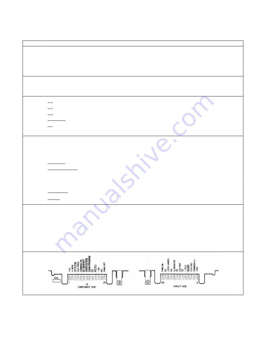
Table 3-9. Control Board Test Connector, A2J7
PIN NO.
SIGNAL NAME
Vdc
WAVEFORM/CONDITIONS
SOURCE
Digital-Circuits Bias & Reference Voltages
1
+5V
5.0
A2Q3 (emitter)
22
+ 20V(5V UNREG)
20.0
with 120Hz & 45KHz ripple
AlCR6, AlCR7
14
2.5V ref
2.50
A2U9 (OUT)
6
0.5V ref
0.50
A2R79,A2R80
Analog-Circuits Bias Voltages
2
+15V
15.0
A2U12 (OUT)
21
-15V
-15.0
A2U4 (OUT )
Status Signals
17
CV
TTL Lo
if in CV operation
A2Q6C-7 (collector)
16
CC
TTL Lo
if in CC operation
A2Q6F-14 (collector)
13
OV
TTL Hi
if not OVP shutdown
A2U11D-11
11
DROPOUT
TTL Hi
if ac mains okay
A2U17D-11
12
OT
TTL Hi
if not overtemp shutdown
A2U11B-6
Control Signals
25
PWM OFF
1.7
µ
s TTL pulses, 20KHz
U1A-5
26
PWM ON
1.7
µ
s TTL pulses, 20KHz
U2B-6
18
Ip MONITOR
1V pk, ½ sawtooth, 20KHz
A2CR26 (cathode)
(at full power only)
8
INHIBIT
TTL Hi
if not remotely inhibited
A2R185C, U19A-2
15
DOWN PROGRAM
1.2-3.0
while not down programming
A2CR21, A2CR27
7
OVP PROGRAM
1/10 OVP (6033A)
e.g.: 2Vdc if OVP set to full
1/30 OVP (6038A)
voltage output
A3R6 (wiper)
5
OV CLEAR
+5V
inverted OV reset line
A8U4-35
19
PCLR2
+5V
if +5V bias OK
A2Q60-9
Commons & Current-Monitor
4
COMMON
0.0
common return for all bias
voltages, status and control
signals
A2C20(-), A2R50
9
COMMON
0.0
common return for 2.5V ref and
0.5V ref
A2R83, A21-20
10
I-TEST
≈
0.005 (6033A).
inboard-side monitoring res
A1R27 &A1R28, A1T2
≈
0.055 (6038A)
3
V-MON-BUF
V-OUT/12
trimmed V-MON for readback
A8U25-6
Summary of Contents for 6038A
Page 4: ......
Page 8: ......
Page 34: ...34 Figure 3 1 Troubleshooting Isolation ...
Page 35: ...35 Figure 3 1 Troubleshooting Isolation continued ...
Page 37: ...37 Figure 3 3 Clock and Primary SA Waveforms ...
Page 40: ...40 Figure 3 4 Readback and Secondary SA Waveforms ...
Page 56: ...56 Figure 3 7 Waveforms ...
Page 62: ...62 Figure 4 1 HP IB Block Diagram ...
Page 65: ...65 Figure 4 2 Front Panel Block Diagram ...
Page 90: ......
Page 93: ...93 Figure 6 1 Top View Top Covers Removed ...
Page 94: ...94 Figure 6 2 Main Board A1 Component Location ...
Page 95: ...95 Figure 6 3 Control Board A2 Component Location ...
Page 96: ...96 Figure 6 4 Front Panel Board A3 Component Location ...
Page 97: ...97 Figure 6 5 Power Mesh Board A4 Component Location ...
Page 98: ...98 Figure 6 6 HP IB Board A8 Component Location ...
Page 105: ...105 Figure 3 1 Troubleshooting Isolation option 001 ...
Page 106: ......


