6-49
Removal and Replacement
CUTTER ENCLOSURE ASSEMBLY REMOVAL
To remove the cutter enclosure assembly, perform the following procedure:
1. Using a TORX T-15 screwdriver, remove the screws that attach the front trim pieces
to the left and right sideplates. Remove the front trim pieces.
2. Remove the overdrive support assembly.
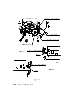
3. Using a TORX T-15 screwdriver, remove the upper of the two screws that attach the
left and right ends of the cutter enclosure assembly to the left and right sideplates.
See Figure 6-32.
4. Using a TORX T-20 screwdriver, loosen the wedge screws at the left and right ends
of the cutter enclosure assembly out of the left and right sideplates until the screws
are flush with the inner side of the sideplates.
5. Pull the cutter enclosure assembly forward and clear of the plotter.
6. To remove the media guides from the cutter enclosure, grasp each one firmly, twist
counter-clockwise, and pull it clear of the enclosure.
Summary of Contents for 650c - DesignJet Color Inkjet Printer
Page 1: ...PrinterFAQ COM HP DesignJet650C User Guide ...
Page 126: ...7 10 Adjustments Calibrations Notes ...
Page 156: ...9 4 Product History Notes ...
Page 165: ...10 9 Parts and Diagrams Illustrated Parts Breakdown C2859A Electronics Enclosure C C2858 3 1 ...
Page 167: ...10 11 Parts and Diagrams Illustrated Parts Breakdown C2858A Electronics Enclosure C C2858 4 1 ...
Page 183: ...10 27 Parts and Diagrams Illustrated Parts Breakdown Paper Drive Assemblies C C2858 12 1 ...
Page 199: ......


