8-21
Troubleshooting
READING THE EEROM TEXT BLOCK
Contents of the EEROM IC are printed during the configuration plot in hexadecimal form.
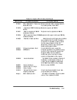
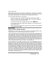
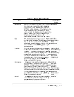
Sample portions of the EEROM contents block and the pen nozzle test block are presented in
the following pages of this chapter to assist you in interpreting the configuration plot results.
To read the EEROM contents block, perform the following steps.
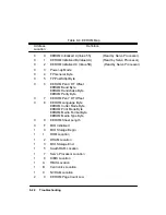
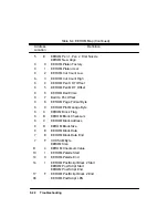
1. Examine the sample EEROM memory map (Table 8-4) to find the memory address
of the data you want to read.
2. Locate the position of the memory address in the contents text block using the
memory location key in Table 8-5.
3. Read the contents of the memory address from the configuration plot EEROM text
block.
Suppose you are interested in knowing the factory platen correction factor. Examining the
EEROM memory map you would find that the memory address of the factory platen correc-
tion factor is 60. Using the memory location key, Table 8-5, you would locate address 60 just
to the right of the ª60º entry. On the sample contents block, Table 8-6, address 60 contains
the factory platen correction factor of hexadecimal number 50.
ANALYZING THE PEN NOZZLE TEST BLOCK
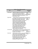
The blocks of numbers on the lower right portion of the plot can be used to determine particu-
lar pen nozzle problems. From left to right, the blocks represent the black, magenta, cyan and
yellow pens.
Each block has a matrix of 5 digit codes. These codes are used to determine a pen nozzle pass
or fail condition. Each code digit represents a pen ªsquirtº test.
For the black pen, all the codes in the block should read 00001, indicating a good pen. If any
of the nozzle position codes read a code of 2 or higher, that pen nozzle is defective.
For the color pens, the codes should read 00005. A code of 5 indicates the pen nozzle passed 5
out of 5 tests. A code of A means the pen nozzle passed 5 out of 10 tests, while a code of 8
means 8 of 10 tests passed. A code of B in the matrix means that particular pen nozzle has
failed the test.
Summary of Contents for 650c - DesignJet Color Inkjet Printer
Page 1: ...PrinterFAQ COM HP DesignJet650C User Guide ...
Page 126: ...7 10 Adjustments Calibrations Notes ...
Page 156: ...9 4 Product History Notes ...
Page 165: ...10 9 Parts and Diagrams Illustrated Parts Breakdown C2859A Electronics Enclosure C C2858 3 1 ...
Page 167: ...10 11 Parts and Diagrams Illustrated Parts Breakdown C2858A Electronics Enclosure C C2858 4 1 ...
Page 183: ...10 27 Parts and Diagrams Illustrated Parts Breakdown Paper Drive Assemblies C C2858 12 1 ...
Page 199: ......


