3-2
Installation and Configuration
INSTALLATION INSTRUCTIONS
USER-INSTALLABLE MODULES
Expansion sockets located behind a panel at the rear of the plotter allow the user to install
additional memory modules. These SIMMs (single in–-line memory modules) are available
in 4MB and 8MB sizes. Installation is accomplished by removing the access panel (4
screws), installing the module(s), and reattaching the access panel. ROM sockets are also
provided for use with ROM enhancements as developed. Installation instructions are pro-
vided with the modules and also provided in Chapter 6 of this manual. Information on order-
ing the memory expansion and ROM modules is provided in Chapter 1 of this manual.
An interface port on the back of the plotter allows the user to select one of several available
modular interfaces at a time. The modular I/O cards can be easily changed to match the de-
sired application. Installation instructions are provided with the modules and also provided
in Chapter 6 of this manual. Information on ordering the modular I/Os is provided in Chapter
1 of this manual.
CONNECTIVITY
Depending upon the interface and hardware being used to drive the plotters, different cables
could be required. A listing of cables and other connectivity related issues is provided in the
DesignJet 650C documentation listed in Chapter 1 of this manual.
LINE VOLTAGE AND FUSING
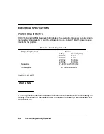
The HP C2858/9A DesignJet 650C plotter’s power supply automatically adjusts to the input
voltage. The plotter’s autoranging power supply accepts an input of 90 to 264 Vac.
POWER CORD CONFIGURATIONS
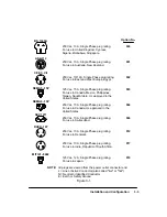
Power cord configurations shipped with the plotter depend upon the country of destination
for the plotter. See Figure 3-1 for information on the power cord configurations available for
use with the plotters. When connecting the plotter to the ac source, ensure that the appropriate
power cord is used.
Summary of Contents for 650c - DesignJet Color Inkjet Printer
Page 1: ...PrinterFAQ COM HP DesignJet650C User Guide ...
Page 126: ...7 10 Adjustments Calibrations Notes ...
Page 156: ...9 4 Product History Notes ...
Page 165: ...10 9 Parts and Diagrams Illustrated Parts Breakdown C2859A Electronics Enclosure C C2858 3 1 ...
Page 167: ...10 11 Parts and Diagrams Illustrated Parts Breakdown C2858A Electronics Enclosure C C2858 4 1 ...
Page 183: ...10 27 Parts and Diagrams Illustrated Parts Breakdown Paper Drive Assemblies C C2858 12 1 ...
Page 199: ......

