3-8
Installation and Configuration
3. Open the roll cover and insert the spindle, with the endcap at the left and the media
stop at the right. Firmly push on both ends. See Figure 3-4.
Figure 3-4.
Roll Cover
Pinchwheel Lever
Installing the Spindle
(C) C2847-31(UM)
4. Once the roll is in place, push the media all the way to the right, so that it’s flush
against the media stop.
5. Ensure that the pinchwheel lever at the right of the plotter is down.
6. Turn the plotter ON, if it is not already ON.
7. Grasp the leading edge of the media and pull about one foot (30 cm) of media out
from the roll. Check the leading edge of the media. If it appears uneven, or to ensure
a straight edge, the edge will need to be trimmed.
W A R N I N G
The cutter blade is very sharp. Use caution when using the
cutter to trim or cut media. Keep hands away from the blade
when cutting. Retract the blade into the cutter after use.
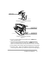
8. Trim the leading edge if it’s uneven. Pull it over the top of the plotter and lay it over
the cutting track. Using the cutter located in the holder at the back of the plotter, cut
off the first few inches of the media. See Figure 3-5. Return the cutter to the holder.
9. Load the leading edge, aligning the right edge with the perforated line on the entry
platen. Push the media in until it buckles slightly as it hits the stops inside the plotter.
Let go when the plotter begins to pull the media in. See Figure 3-6.
Summary of Contents for 650c - DesignJet Color Inkjet Printer
Page 1: ...PrinterFAQ COM HP DesignJet650C User Guide ...
Page 126: ...7 10 Adjustments Calibrations Notes ...
Page 156: ...9 4 Product History Notes ...
Page 165: ...10 9 Parts and Diagrams Illustrated Parts Breakdown C2859A Electronics Enclosure C C2858 3 1 ...
Page 167: ...10 11 Parts and Diagrams Illustrated Parts Breakdown C2858A Electronics Enclosure C C2858 4 1 ...
Page 183: ...10 27 Parts and Diagrams Illustrated Parts Breakdown Paper Drive Assemblies C C2858 12 1 ...
Page 199: ......

