6-38
Removal and Replacement
PEN CARRIAGE ASSEMBLY AND MAIN DRIVE BELT REMOVAL
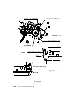
To remove the pen carriage assembly, see Figure 6-26 and perform the following procedure:
1. Remove the window assembly.
2. Remove the left and right endcovers.
3. Disconnect the trailing cable from the carriage PCA.
4. Using a TORX T-15 screwdriver, remove the screw that secures the trailing cable
bracket to the pen carriage assembly and lift the trailing cable assembly clear of the
pen carriage assembly.
5. Remove the trailing cable guide.
6. Remove the encoder strip.
7. Remove the Y-tensioner and housing.
8. Slide the main idler out of the housing.
9. Remove the encoder spring-bracket.
10. Remove the double pulley from the Y-drive bracket. While doing this keep the palm
of one hand beneath the double pulley to catch the double-pulley bushing.
11. Using a TORX T-20 screwdriver, remove the three screws that attach the Y-drive
bracket to the sideplate. Position the Y-drive bracket assembly out of the way, so that
the pen carriage assembly can be removed.
12. Remove the cutter assembly making sure to hold the rear cutter bushing and spring
in place while removing the cutter.
13. Remove the pen carriage assembly with main drive belt from the plotter.
14. Set the pen carriage assembly top side down on a flat surface.
15. Using a small, standard screwdriver, remove the left and right belt clamps from the
pen carriage assembly.
16. Remove the main drive belt from the pen carriage assembly.
When reinstalling the encoder strip, remember to properly adjust the strip so that it does not
touch the pen carriage assembly. To adjust, loosen the encoder spring-bracket screws and
move the bracket up or down as necessary to center the strip in the pen carriage apertures.
Summary of Contents for 650c - DesignJet Color Inkjet Printer
Page 1: ...PrinterFAQ COM HP DesignJet650C User Guide ...
Page 126: ...7 10 Adjustments Calibrations Notes ...
Page 156: ...9 4 Product History Notes ...
Page 165: ...10 9 Parts and Diagrams Illustrated Parts Breakdown C2859A Electronics Enclosure C C2858 3 1 ...
Page 167: ...10 11 Parts and Diagrams Illustrated Parts Breakdown C2858A Electronics Enclosure C C2858 4 1 ...
Page 183: ...10 27 Parts and Diagrams Illustrated Parts Breakdown Paper Drive Assemblies C C2858 12 1 ...
Page 199: ......

