The
master
determines
its
slav
e-area
b oundaries
b
y
rst
searc
hing
up
w
ard
in
its
o
wn
column
starting
in
the
master's
row,
then
in
eac
h
higher
column
starting
in
the
master's
row.
The
searc
h
stops
at
the
b oundary
column
or,
if
there
is
no
dening
elemen
t,
after
searc
hing
column
31.
The
master
uses
the
follo wing
criteria
to
set
slav
e
area
b oundaries.
1.
The
left
b oundary-column
equals
the
master's
column
address.
2.
If
there
is
a
dening
elemen
t
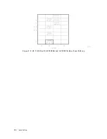
(see
Figure
2-5),
the
right
b oundary-column
equals
the
dening
elemen
t's
column
address
min
us
one.
3.
If
there
is
no
dening
elemen
t,
the
right
b oundary
column
is
column
31.
4.
The
top
b oundary
is
row
7.
Address
Switches
The
address
switches
set
an
elemen
t's
HP-MSIB
address.
If
the
elemen
t
is
a
master
or
an
indep enden
t
elemen
t,
the
column
switches
also
determine
the
default
HP-IB
address.
(Displays
do
not
ha
v
e
row
address
switches,
so
they
are
alwa
ys
set
to
row
address
0.)
HP
70301A
Address
Switches
There
is
an
eigh
t-section
address
switch
on
top
of
the
HP
70301A.
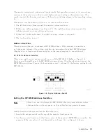
Refer
to
Figure
2-6 .
Sections
one
through
v
e
set
the
HP-MSIB
column
address.
The
three
fron
t
sections
set
the
HP-MSIB
row
address.
Figure
2-6
sho
ws
address
row
5,
column
19,
the
factory
setting
for
the
HP
70301A.
Figure
2-6.
Typical
Address
Switch
Setting
the
HP-MSIB
Address
Switches
Note
There
is
no
need
to
c
hange
the
HP
70301A's
factory-preset
address
unless
other
mo
dules
in
the
system
do
not
ha
v
e
their
factory-preset
addresses.
A
mo
dule-address
c
hange
requires
the
follo wing
steps:
1.
Lo cate
the
address
switch
on
the
top
of
the
mo
dule.
See
Figure
2-6 .
2.
Set
the
row
switch
sections
to
the
binary
v
alue
of
the
mo
dule's
HP-MSIB
row
n
um
b er.
F
or
example,
if
the
row
v
alue
is
5,
set
the
switches
to
binary
101,
as
Figure
2-6
sho
ws.
Installation
2-9
Summary of Contents for 70301A
Page 6: ......
Page 10: ......
Page 16: ...Figure 1 2 Front Panel and Rear Panel Features 1 6 General Information ...
Page 20: ...Figure 1 3 Packaging Materials for HP 70001A Mainframe 1 10 General Information ...
Page 21: ...Figure 1 4 Packaging Materials for Modules General Information 1 11 ...
Page 26: ......
Page 32: ...Figure 2 3 HP 71210C with HP 70300A and HP 70301A Rear Panel Cabling 2 6 Installation ...
Page 50: ......
Page 58: ......

