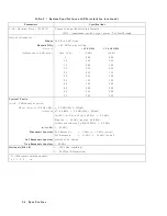
TG
Feedthru
(HP
70301A)
(using
HP
70902A
or
HP
70903A)
T
ested
Specification
T
rac
king
Generator
F
eedthrough
Equipment
P
o
w
er
Meter
RF
P
o
w
er
Sensor
50
Ohm
T
ermination
(HP
909D
only)
Note
The
t
yp e
of
50
termination
used
can
greatly
aect
the
feedthrough
lev
el.
BNC
or
T
yp e
N
terminations
ha
v
e
to
o
m
uc
h
leak
age,
and
should
not
b e
used.
The
leak
age
of
the
HP
909D
termination
is
low
enough
not
to
aect
the
measuremen
t.
Equipment
Setup
Setup
A:
Connect
the
RF
OUTPUT
of
the
tracking
generator
to
the
RF
INPUT
of
the
sp ectrum-analyzer
system.
Setup
B:
With
the
RF
p o
w
er-sensor
output
connected
to
the
p o
w
er
meter,
connect
the
input
of
the
RF
p o
w
er
sensor
to
the
RF
OUTPUT
of
the
tracking
generator.
Connect
the
50
ohm
termination
to
the
RF
INPUT
of
the
sp ectrum
analyzer.
Description
The
equipmen
t
is
connected
using
setup
A.
The
sp ectrum
analyzer
system
con
taining
the
tracking
generator
is
placed
in
Stimulus
Resp onse
mo
de
and
set
to
the
minimum
IF
resolution
bandwidth
(10
Hz,
HP
70902A;
100
kHz,
HP
70903A).
Source
track
p eaking
is
then
p erformed
to
make
sure
that
the
source
frequency
is
cen
tered
in
the
IF
resolution
bandwidth.
The
equipmen
t
is
connected
using
setup
B.
The
tracking
generator
feedthrough
lev
el
is
then
measured
in
eac
h
band
of
the
sp ectrum
analyzer
using
the
follo
wing
pro cedure:
1.
The
tracking
generator
is
set
for
an
RF
output
of
010
dBm.
2.
The
sp ectrum
analyzer
is
set
as
follo ws:
Reference
lev
el:
HP
70902A:
065
dBm
( 075
dBm
when
HP
70908A
is
RF
section).
HP
70903A:
025
dBm
( 035
dBm
when
HP
70908A
is
RF
section).
Resolution
bandwidth:
HP
70902A:
10
Hz.
HP
70903A:
100
kHz.
A
tten
uator
setting
of
0
dB.
Sample
detection.
Stop
and
start
frequencies
are
set
for
the
band
of
in
terest.
3.
A
sw
eep
is
taken.
4-6
V
erification
Summary of Contents for 70301A
Page 6: ......
Page 10: ......
Page 16: ...Figure 1 2 Front Panel and Rear Panel Features 1 6 General Information ...
Page 20: ...Figure 1 3 Packaging Materials for HP 70001A Mainframe 1 10 General Information ...
Page 21: ...Figure 1 4 Packaging Materials for Modules General Information 1 11 ...
Page 26: ......
Page 32: ...Figure 2 3 HP 71210C with HP 70300A and HP 70301A Rear Panel Cabling 2 6 Installation ...
Page 50: ......
Page 58: ......


