background image

Operating

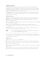
Errors

(2000-2999)

Op erating

errors

result

from

incorrect

use

of

the

analyzer,

usually

during

remote

op eration.

The

op eration

and

programming

man

uals

explain

man

ual

and

remote

analyzer

op eration.

2001

Illegal

cmd

(Illegal

command)

|

User-generated

system

proto

col

error.

This

error

o ccurs

when

the

mo

dule

encoun

ters

a

command

it

do es

not

recognize.

This

can

b e

caused

b

y

the

master

elemen

t's

sending

suc

h

a

command,

a

problem

in

ternal

to

the

mo

dule,

or

an

op en

cable

b et

w

een

the

master

and

mo

dule.

The

problem

can

b e

isolated

b

y

substituting

master,

mainframe,

or

mo

dules.

2002

Illegal

parameter

|

Description

of

error

2001

applicable

to

error

2002.

2006

Parm

out

of

range

|

Description

of

error

2001

applicable

to

error

2006.

2008

Output

unleveled

|

Setting

the

output

p o

w

er

ab o

v

e

the

sp ecied

maximum

lev

eled

output

p o

w

er

(0

dBm

for

20-30

C)

may

cause

error

2008.

This

error

will

also

o ccur

if

EXT

detector

(ALC

EXT)

is

selected

with

no

external

detector

connected

to

the

fron

t

panel

EXT

ALC

INPUT.

The

source

p o

w

er

from

the

HP

70301A

T

rac

king

Generator

is

unlev

eled

(outside

the

range

of

the

ALC

circuit).

The

selected

output

p o

w

er

may

b e

set

ab o

v

e

0

dBm

for

20-30

C.

If

the

p o

w

er

setting

is

within

range,

susp ect

the

follo

wing

assem

blies:

A7

ALC/Bias

PC

Board.

A8A3

ALC

Micro

circuit.

A8A3A1W1

In

ternal

detector

coaxial

cable.

W6

EXT

ALC

INPUT

coaxial

cable,

if

error

2008

o ccurs

with

ALC

EXT

selected.

2009

Protocol

error

|

Description

of

error

2001

applicable

to

error

2002.

Hardw

are

W

arning

Errors

(6000-6999)

These

error

co des

rep ort

the

status

of

the

HP

70301A

hardw

are.

An

error

indicates

that

some

of

the

hardw

are

is

not

functioning

prop erly

.

Measuremen

t

accuracy

may

b e

impaired.

6000

EAROM

unprotected

|

The

EAR

OM

write

protect/enable

switch

on

the

con

troller

PC

b oard

is

in

the

enable

p osition.

Hardw

are

Brok

en

Errors

(7000-7999)

These

error

co des

are

generated

b

y

hardw

are

or

rm

w

are

failures

within

the

mo

dule

and

are

usually

catastrophic

to

op eration

of

the

mo

dule.

7000

ROM

Check

error

|

The

programmed

c

hec

ksum

of

the

low

er

t

w

o

kilobytes

of

EAR

OM

do es

not

agree

with

the

computed

c

hec

ksum.

First

susp ect

the

A3U4

EAR

OM

then

the

A3

Con

troller

Board

Assem

bly

.

7002

First

LO

unleveled

|

The

Lo cal

Oscillator

signal

from

the

lo

cal

oscillator

mo

dule

is

missing

or

not

correct.

V

erify

that

rear-panel

cabling

is

correct.

If

the

cables

are

correct,

the

follo

wing

assem

blies

are

most

susp ect:

A8A7

LO

lev

eling

amp

A7

ALC/Bias

Board

Assem

bly

A8A5

Isolator

W3

LO

input

coaxial

cable

5-6

Troubleshooting

Summary of Contents for 70301A

Page 1: ...Installation and Verification Manual HP 70301A Tracking Generator ABCDE HP Part No 70301 90039 Printed in USA June 1992 Edition B 0 0 ...

Page 2: ...of this material Restricted Rights Legend Use duplication or disclosure by the U S Government is subject to restrictions as set forth in subparagraph c 1 ii of the Rights in Technical Data and Computer Software clause at DFARS 252 227 7013 for DOD agencies and subparagraphs c 1 and c 2 of the Commercial Computer Software Restricted Rights clause at FAR 52 227 19 for other agencies c Copyright Hewl...

Page 3: ... another country Hewlett Packard warrants that its software and rmware designated by Hewlett Packard for use with an instrument will execute its programming instructions when properly installed on that instrument Hewlett Packard does not warrant that the operation of the instrument or software or rmware will be uninterrupted or error free Limitation of Warranty The foregoing warranty shall not app...

Page 4: ...N sign until the indicated conditions are fully understood and met WARNING The WARNING sign denotes a hazard It calls attention to a procedure which if not correctly performed or adhered to could result in injury to the user Do not proceed beyond a WARNING sign until the indicated conditions are fully understood and met DANGER The DANGER sign denotes an imminent hazard to people It warns the reade...

Page 5: ...the protective conductor inside or outside of the instrument is likely to make the instrument dangerous Intentional interruption is prohibited For continued protection against fire hazard replace fuse only with same type and ratings type nA nV The use of other fuses or materials is prohibited WARNING Before this instrument is switched on make sure it has been properly grounded through the protecti...

Page 6: ......

Page 7: ...F OUTPUT 1 4 Module Latch 1 4 Rear Panel Features 1 4 3 6 6 6 GHz LO IN 1 4 3 6 6 6 GHz LO OUT 1 4 300 MHz IN 1 4 300 MHz OUT 1 5 21 4 MHz IN 1 5 21 4 MHz OUT 1 5 TUNE SPAN IN 1 5 Mainframe Module Interconnect 1 5 HP 70900 Local Oscillator Firmware 1 7 Options and Accessories 1 7 Options 1 7 Accessories Provided with the HP 70301A 1 8 Service Kit 1 8 Initial Inspection 1 8 Returning Instruments fo...

Page 8: ...peci cations Introduction 3 1 System Speci cations and Characteristics 3 2 4 Veri cation Introduction 4 1 Explanation of Test Descriptions 4 1 Test Descriptions 4 2 TG Absolute Amplitude Accuracy HP 70301A 4 3 TG Vernier Accuracy HP 70301A 4 4 TG Frequency Response HP 70301A 4 5 TG Feedthru HP 70301A 4 6 5 Troubleshooting Introduction 5 1 Troubleshooting Features 5 1 1 Indicator Lights 5 1 2 Statu...

Page 9: ...ddress Switch 2 9 Tables 1 1 Accessories Shipped with the HP 70301A 1 8 1 2 ESD Accessories Available from HP Sales and Service O ces 1 13 1 3 ESD Accessories Available from HP Computer Supplies 1 14 1 4 Hewlett Packard Sales and Service O ces 1 15 2 1 HP 70000 Modular Measurement System Rear Panel Cables 2 3 2 2 Decimal Equivalent of Binary Address 2 8 3 1 System Speci cations and Characteristics...

Page 10: ......

Page 11: ...erformance veri cation tests that are on Disk 3 provided with this manual Chapter 5 Troubleshooting describes LED indicators software tools and error codes generated by the HP 70301A Chapter 1 Topics A brief description of the HP 70301A Mechanical features of the HP 70301A Local oscillator rmware compatibility Available options Initial inspection Packaging the module for shipping Preventing damage...

Page 12: ...l represents a key physically located on the instrument This key is referred to as either a key or a hardkey NNNNNNNNNNNNNNNNNNNNNNN Firmkey A screen font word with an uppercase rst letter indicates a top level softkey referred to as a rmkey A rmkey accesses a related sub menu of softkeys For example pressing 4MENU5 causes rmkey labels to appear on the left side of the display and related softkey ...

Page 13: ...al Updating Supplement The front cover of the supplement provides applicable model number manual print date and manual part number For o ce locations see Table 1 4 at the end of this chapter Front Panel and Rear Panel Features Figure 1 2 illustrates front and rear panel features Front Panel Features ERR If the error LED lights at any time other than during self test there is a problem with the HP ...

Page 14: ... is the external leveling signal when an external detector is providing automatic level control RF OUTPUT The signal available at this Type N f connector is the HP 70301A RF output Module Latch The module latch secures the module in a mainframe An 8 mm hex ball driver shipped with the mainframe ts the module hex nut latch Chapter 2 provides instructions for installation and removal of a module Rea...

Page 15: ... signal available at this SMB m connector comes from an oscillator internal to the HP 70301A The signal is normally cabled to the 21 4 MHz IN connector TUNE SPAN IN The voltage applied to this SMB m connector normally comes from the local oscillator TUNE SPAN connector The tune span voltage pretunes he YTO and drives the dynamic leveling of the HP 70301A output signal Mainframe Module Interconnect...

Page 16: ...Figure 1 2 Front Panel and Rear Panel Features 1 6 General Information ...

Page 17: ...ppears in the display s general annotation block Options and Accessories Options W30 Option adds two years additional return to Hewlett Packard warranty Option 001 Deletes 55 dB step attenuator Option 910 Extra copy of this manual and the HP 70300A 70301A Operation Manual Option 915 Service manual with veri cation software Option 098 or Option 099 System LO Firmware Upgrade Contact the Marketing D...

Page 18: ...61 9038 Connector Adapter SMB tee m m f 1 6 1250 1391 Service Kit The HP 70000 System Service Kit is the general service kit for HP 70000 Series modules This kit includes servicing tools required to repair all HP 70000 Series modules and also a modi cation procedure for the HP 70001A Mainframe The modi cation allows access to HP 70000 Series modules during bench testing and repair Initial Inspecti...

Page 19: ... Name and telephone number of technical contact person d Return address e Model number of returned instrument f Full serial number of returned instrument g List of any accessories returned with instrument 2 To help prevent damage during transit pack the instrument in the appropriate packaging materials as shown in Figure 1 3 and Figure 1 4 Original shipping materials or equivalents are best howeve...

Page 20: ...Figure 1 3 Packaging Materials for HP 70001A Mainframe 1 10 General Information ...

Page 21: ...Figure 1 4 Packaging Materials for Modules General Information 1 11 ...

Page 22: ...The Static Safe Accessories section provides lists of accessories Figure 1 5 Static Safe Workstation Reducing ESD Damage The following suggestions help reduce ESD damage that can occur during instrument test and service PC Board Assemblies and Electronic Components Work at a static safe workstation Store or transport in static shielding containers Do not use erasers to clean edge connector contact...

Page 23: ...sts static safe accessories that are available from any Hewlett Packard o ce Table 1 3 lists accessories available from the Hewlett Packard Computer Supplies Operations Table 1 2 ESD Accessories Available from HP Sales and Service Offices Description Qty CD HP Part Number 3M static control mat 0 6 m21 2 m 2 ft24 ft and 4 6 m 15 ft ground wire The wrist strap and wrist strap cord are not included T...

Page 24: ...8m x 1 2m 6 ft x 4 ft natural 92176A Antistatic carpet 1 8m x 1 2m 6 ft x 4 ft russet 92176C Antistatic carpet 2 4m x 1 2m 8 ft x 4 ft natural 92176B Antistatic carpet 2 4m x 1 2m 8 ft x 4 ft russet 92176D Sales and Service Offices Hewlett Packard Sales and Service O ces provide worldwide support for Hewlett Packard products To obtain servicing information or to order replacement parts contact the...

Page 25: ...49 5000 6 907 78 25 IN SINGAPORE Georgia IN GERMAN FEDERAL Hewlett Packard Singapore Hewlett Packard Co REPUBLIC Pte Ltd 2000 South Park Place Hewlett Packard GmbH 1150 Depot Road P O Box 105005 Vertriebszentrale Frankfurt Singapore 0410 Atlanta GA 30339 Berner Strasse 117 273 7388 404 955 1500 Postfach 560 140 Telex HPSGSO RS34209 D 6000 Frankfurt 56 Fax 65 2788990 Illinois 0611 50 04 1 Hewlett P...

Page 26: ......

Page 27: ...t door See Figure 2 1 2 Verify correct module HP MSIB addressing as explained in this chapter under HP MSIB HP IB Addressing 3 Slide the module into the mainframe then use the 8 mm hex ball driver to tighten the module latch The HP 70301A obtains both power and interface bus control through the module rear panel mainframe module interconnect Swing the front door up 4 Connect rear panel cabling For...

Page 28: ...s by cycling the power Most plotters and printers can be reset with the front panel reset keys or by turning the main power o then on 8 Check HP MSIB addressing by pressing 4DSP5 and NNNNNNNNNNNNNNNNNNNNNNNNNNNNNNNNNNN ADDRESS MAP Each address consists of a row number and a column number 9 Verify module operation using test described in Chapter 4 Figure 2 1 Module Removal Replacement Removal 1 Set...

Page 29: ...021 5449 2 2 L to R 5021 5450 5 3 L to R 5021 5451 6 4 L to R 5021 5452 7 5 L to R 5021 5453 8 6 L to R 5021 5454 9 7 L to R 5021 5491 4 1 R to L 5021 5492 5 2 R to L 5021 5493 6 3 R to L 5021 5494 7 4 R to L 5021 5495 8 5 R to L 5021 5496 9 6 R to L 5021 5497 0 7 R to L Flexible LO I O 5061 9038 7 520 mm 5061 9039 8 745 mm Flexible System 5061 9015 0 1 90 mm 5061 9016 1 2 140 mm 5061 9017 2 3 190...

Page 30: ...00C with HP 70300A and HP 70301A The HP 70001A mainframe does not have an HP MSIB address The usual address for the HP 70004A display is Row 0 Column 4 Refer to Chapter 1 for information about software rmware compatibility CAUTION To ensure proper electrical connection and prevent connector damage all APC 3 5 and SMA connectors must be torqued 5 to 8 inch pounds nger tight Do not exceed 8 inch pou...

Page 31: ...E SPAN 8120 5021 310 mm HP 70908A TUNE SPAN HP 70300A TUNE SPAN 8120 5017 205 mm HP 70300A TUNE SPAN HP 70301A TUNE SPAN 8120 5017 205 mm HP 70908A 21 4 MHZ OUT HP 70903A 21 4 MHZ IN 8120 5022 365 mm HP 70902A VIDEO OUT HP 70903A VIDEO IN 8120 5014 100 mm HP 70902A 21 4 MHZ IN HP 70903A 21 4 MHZ OUT 8120 5014 100 mm HP 70300A 300 MHZ OUT HP 70301A 300 MHZ IN 8120 5016 160 mm HP 70301A 21 4 MHZ IN ...

Page 32: ...Figure 2 3 HP 71210C with HP 70300A and HP 70301A Rear Panel Cabling 2 6 Installation ...

Page 33: ...ssing and the structural relationships among modular measurement system devices Functional Terms Element Any device that communicates over the HP MSIB The HP 70001A Mainframe controls all communications over HP MSIB but does not communicate over HP MSIB therefore the mainframe is not an element Slave An element controlled by another element Master An element that controls other elements Sub Master...

Page 34: ...Address Matrix Each element must have a unique 8 bit binary HP MSIB address correctly placed on the address matrix The three most signi cant bits MSB determine the row address the ve least signi cant bits LSB the column address This manual refers to the decimal equivalent of a binary address see Table 2 2 Table 2 2 Decimal Equivalent of Binary Address Row MSB Column LSB Binary 010 11000 Decimal 2 ...

Page 35: ...lumn switches also determine the default HP IB address Displays do not have row address switches so they are always set to row address 0 HP 70301A Address Switches There is an eight section address switch on top of the HP 70301A Refer to Figure 2 6 Sections one through ve set the HP MSIB column address The three front sections set the HP MSIB row address Figure 2 6 shows address row 5 column 19 th...

Page 36: ...xample if the column value is 19 set the switches to binary 10011 as Figure 2 6 shows Note Changing HP MSIB addresses requires an understanding of HP MSIB addressing rules For help with custom con guration addressing refer to the system master installation and veri cation manual 2 10 Installation ...

Page 37: ...ce over the temperature range of 0 C to 50 C after one hour of continuous operation unless otherwise noted Speci cations apply after the system temperatures have stabilized and self calibration routines have run The standard Hewlett Packard operating temperature range is 0 C to 55 C the HP 70301A is an exception Unless otherwise noted corrected limits are given when a speci cation range is improve...

Page 38: ...d measurement related speci cations for HP 71000 MMS Microwave Spectrum Analyzers with an HP 70301A Tracking Generator module For more information on di erent system con gurations please refer to the HP 71000 MMS Spectrum Analyzer HP 70900 Installation and Veri cation Manual 3 2 Specifications ...

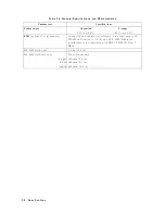
Page 39: ...tal Total Abs Accuracy 0 dB attn 62 3 dB absolute accuracy atness vernier Amplitude Drift 60 05 dB C at 02 dBm output power Tracking Generator Feedthrough System Performance Less than 130 dBm or standard system displayed average noise level without HP 70301A whichever is greater disregarding the exceptions listed below Note Systems with preampli ers will not meet this speci cation Exceptions HP 71...

Page 40: ... 25 0 95 1 15 30 0 90 1 20 35 1 25 1 60 40 1 80 2 00 45 2 00 2 20 50 2 00 2 30 55 2 20 2 50 Spectral Purity with 02 dBm output power Phase Noise at 10 kHz o set 90 dBc Hz 20logN Sidebands ny240 kHz 70 dBc Hz 20logN n250 n260 and n2400 Hz 050 dBc Display 060 dBc approx 24 kHz Others contributed by HP 70301A 080 dBc n21st LO 065 dBc Harmonic Spurious 2nd harmonic 07 dBc 015 dBc typical 3rd harmonic ...

Page 41: ...oss 4 0 dB Table 3 3 HP 70301A Input and Output Characteristics Rear Panel Connectors HP 70301A Characteristics LO IN SMA female 2 1 VSWR 3 6 6 GHz 0 5 to 18 0 dBm required Maximum Safe Input Level 20dBm 5 V dc LO OUT SMA female 3 1 VSWR 3 6 6 GHz 3 0 to 15 0 dBm Maximum Safe Reverse Level 20 dBm 6 5 V dc 300 MHz IN SMB male 300 60 03 MHz 2 to 02 dBm 300 MHz OUT SMB male 0 61 dBm 25 dBc Harmonics ...

Page 42: ...pplies to systems only Conducted and radiated interference is in compliance with CISPR publication 11 1975 and FTZ 1046 Radiated interference is in compliance with MIL STD 461B Part 7 RE02 HP 70301A Weight 6 9 kg 15 2 lb HP 70301A Dimensions 3 8 width module height 127 mm 5 0 in width 144 mm 5 7 in length 467 mm 18 4 in 3 6 Specifications ...

Page 43: ...di cation of operation veri cation software Rev B 02 00 or B 02 01 The UPDATE program on HP 70301A Test Disk 3 provides these changes Explanation of Test Descriptions The next section describes veri cation tests provided on Disk 3 The following list explains the information found under the test descriptions Tested Speci cation is the name of the speci cation as found in the Speci cations chapter o...

Page 44: ... lists tracking generator tests described in this section and included on the HP 70301A Test Disk 3 Table 4 1 is an extension to a similar table in the HP 70900B installation and veri cation manual Table 4 1 Tracking Generator Operation Verification Tests Operation Veri cation Test Page Absolute Amplitude Accuracy 4 3 Vernier Accuracy 4 4 Frequency Response 4 5 Feedthru 4 6 4 2 Verification ...

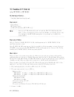
Page 45: ...he MW power sensor to the RF OUTPUT of the tracking generator Description This test measures the absolute RF output amplitude accuracy of the tracking generator at its maximum speci ed leveled output power The tracking generator frequency is set at 2 7 GHz and the output amplitude is set to 02 dBm Then the output power is measured In Case of Failure If this test fails the following modules may nee...

Page 46: ... generator frequency is set to 2 7 GHz and the tracking generator s attenuator if present is set to 0 dB The tracking generator output power is then set to 0 dBm and a reference reading is taken with the power meter The output power is then stepped in 1 dB increments over the 011 dBm to 01 dBm range The absolute error between the programmed amplitude what was expected and the power meter reading w...

Page 47: ... the tracking generator over its complete frequency range The tracking generator is set to a frequency of 2 7 GHz then a power meter is used to set the tracking generator output amplitude to 02 dBm 60 15 dB This establishes the reference amplitude The tracking generator is then incremented in frequency the output power is read by the power meter and the variation from the reference amplitude is st...

Page 48: ...zer Description The equipment is connected using setup A The spectrum analyzer system containing the tracking generator is placed in Stimulus Response mode and set to the minimum IF resolution bandwidth 10 Hz HP 70902A 100 kHz HP 70903A Source track peaking is then performed to make sure that the source frequency is centered in the IF resolution bandwidth The equipment is connected using setup B T...

Page 49: ...o 0 Hz Video bandwidth is set to 3 Hz Sweep time is set to a value which assures that the trace data elements are uncorrelated 6 A sweep is taken The tracking generator feedthrough level is equal to the average of the trace elements This procedure is repeated for each band of the spectrum analyzer In Case of Failure If this test fails the following modules may need repair or adjustment Tracking Ge...

Page 50: ......

Page 51: ...isted in Chapter 2 under Modular Measurement System Terminology The modular spectrum analyzer has the following troubleshooting features 1 Indicator lights 2 Status Indicators 3 Programs a Power On Self Test b System Diagnostics c Module Veri cation d System Performance Programs e System Analyzer Operation Veri cation 4 Error message reports 1 Indicator Lights UNLEVELED This LED indicates that the...

Page 52: ...isfactorily completed If the error indicator LED of more than one of the spectrum analyzer s modules simultaneously ash at a 1 Hz rate refer to the installation and veri cation manual of the system master Some errors may only be present when the spectrum analyzer is sweeping These errors cause the error indicator to ash at the sweep rate Note It is possible that the error indicator may not be ashi...

Page 53: ...00 Series system not HP 70000XL Series shipped to a customer The primary purpose of System Diagnostics is to detect catastrophic failure in the spectrum analyzer and to determine the nature of the failure A catastrophic failure is a failure which renders the instrument unusable A secondary purpose of System Diagnostics is to determine if any soft failures have occurred and to diagnose to the modul...

Page 54: ...ysis personality software after completion of diagnostics c Module Veri cation There is speci c module veri cation software for the HP 70301A Tracking Generator This HP 70301A Module Veri cation software includes both adjustments and veri cation tests to ensure performance Contact the nearest HP Sales and Service O ce for details d System Performance It is possible to check the calibration and ove...

Page 55: ...s Table 5 1 Error Message Grouping Type Numbers User Application 0001 to 0999 Usage Operating 2000 to 2999 Hardware Warning 6000 to 6999 Hardware Broken 7000 to 7999 Computation 8000 to 8999 Factory Use Only 9000 to 9999 Display Disruptive not numbered System Diagnostic messages use numbers in the 0001 to 0999 range All but the rst and last two categories report the element number and HP MSIB addr...

Page 56: ...e 0 dBm for 20 30 C If the power setting is within range suspect the following assemblies A7 ALC Bias PC Board A8A3 ALC Microcircuit A8A3A1W1 Internal detector coaxial cable W6 EXT ALC INPUT coaxial cable if error 2008 occurs with ALC EXT selected 2009 Protocol error Description of error 2001 applicable to error 2002 Hardware Warning Errors 6000 6999 These error codes report the status of the HP 7...

Page 57: ...o kilobytes of EAROM does not agree with the computed checksum First suspect the A3U4 EAROM then the A3 Controller Board Assembly 7078 Tune Span error The Tune Span voltage is missing or not correct Verify that the correct cable is connected to the rear panel TUNE SPAN IN connector Verify that there is a cable connecting TUNE SPAN IN to A4J1 on the A4 Phase Lock Loop Board Assembly If the cables a...

Page 58: ......

Page 59: ...scillator 1 7 Firmware 1 7 I Indicator Lights RF 5 1 UNLEVELED 5 1 initial inspection 1 8 installing the HP 70301A 2 1 M manual coverage 1 2 errors in the manual 1 2 modi ed modules 1 2 serial numbers 1 2 updating 1 2 Module veri cation software 5 4 O options 1 7 P panel features 1 3 front panel 1 3 LEDs 1 3 module latch 1 3 rear panel 1 3 RF INPUT 1 3 RF OUTPUT 1 3 problems User Screen softkeys m...

Page 60: ... characteristics 3 1 element 2 7 independent 2 7 instrument 2 7 mainframe 2 7 master 2 7 module 2 7 slave 2 7 speci cations 3 1 stand alone instrument 2 7 sub master 2 7 Test Calibration 5 4 Module performance 5 4 Operation Veri cation 5 4 Self Test 5 3 System Diagnostics 5 3 System performance 5 4 troubleshooting 5 1 module level 5 1 U User Screen softkeys 2 2 User Screen softkeys not present 2 2...

Reviews: