background image

Notice 

Hewlett-Packard to Agilent Technologies Transition

To contact Agilent Technologies please use the information below.

Online assistance:


http://www.agilent.com/find/assist

Americas

Canada


1 877 894 4414

Latin America


(305) 269 7500

United States


1 800 829 4444

Asia Pacific

Australia


1 800 629 485

China


800 810 0189

Hong Kong


800 938 693

India


1 800 112 929

Japan


0 120 (421) 345

Korea


080 769 0800

Malaysia


1 800 888 848

Singapore


1 800 375 8100

Taiwan


0800 047 866

Thailand


1 800226 008

Europe & Middle East

Austria


43 (0) 1 360 277 1571

Belgium


32 (0) 2 404 93 40

Denmark


45 70 13 15 15

Finland


358 (0) 10 855 2100

France


0825 010 700*


*0.125 Euros/minute

Germany


49 (0) 7031 464 6333

Ireland


1890 924 204

Israel


972-3-9288-504/544

Italy


39 02 92 60 8484

Netherlands


31 (0) 20 547 2111

Spain


34 (91) 631 3300

Sweden


0200-88 22 55

Switzerland


0800 80 53 53

United Kingdom


44 (0) 118 9276201

Other European Countries: 

http://www.agilent.com/find/contactus

This manual may contain references to HP or Hewlett-Packard. Please note that Hewlett-Packard’s 
former test and measurement, semiconductor products and chemical analysis businesses are now part of 
Agilent Technologies. To reduce potential confusion, the only change to product numbers and names has 
been in the company name prefix: where a product name/number was HP XXXX the current name/
number is now Agilent XXXX. For example, model number HP8648 is now model number Agilent 

8648.

Please note that this document was updated in April 2011 to revise the Mixer Non-Linearity
Table 14-13 on page 14-37.

Summary of Contents for 70427A

Page 1: ...31 464 6333 Ireland 1890 924 204 Israel 972 3 9288 504 544 Italy 39 02 92 60 8484 Netherlands 31 0 20 547 2111 Spain 34 91 631 3300 Sweden 0200 88 22 55 Switzerland 0800 80 53 53 United Kingdom 44 0 118 9276201 Other European Countries http www agilent com find contactus This manual may contain references to HP or Hewlett Packard Please note that Hewlett Packard s former test and measurement semic...

Page 2: ...HP 70427A HP 70428A including Opt 002 Serial Numbers HP 70427A 3240A and Above HP 70428A 3240A and Above User s Guide HP part number 70427 90002 Printed in USA June 2014 Supercedes May 2014 ...

Page 3: ...shed by Hewlett Packard This document contains proprietary information which is protected by copyright All rights are reserved No part of this document may be photocopied reproduced or translated to another language without prior written consent of Hewlett Packard Company Restricted Rights Legend Use duplication or disclosure by the U S Government is subject to restrictions as set forth in subpara...

Page 4: ... Tunable Source Operation Chapter 6 Reference Chain Configuration Chapter 7 Remote Programming Chapter 8 Advanced Hardware Control Chapter 9 Technical Data Chapter 10 Softkeys and Displays Chapter 11 Connectors and Indicators Front and Rear Panel Chapter 12 Remote Programming Commands Chapter 13 Block Diagram Chapter 14 Performance Tests Chapter 15 Adjustments Chapter 16 Customer Support ...

Page 5: ...charge within HP service travel areas Outside HP service travel areas warranty service will be performed at Buyer s facility only upon HP s prior agreement and Buyer shall pay HP s round trip travel expenses In all other areas products must be returned to a service facility designated by HP For products returned to HP for warranty service Buyer shall prepay shipping charges to HP and HP shall pay ...

Page 6: ...FOR ANY DIRECT INDIRECT SPECIAL INCIDENTAL OR CONSEQUENTIAL DAMAGES WHETHER BASED ON CONTRACT TORT OR ANY OTHER LEGAL THEORY Assistance Product maintenance agreements and other customer assistance agreements are available for Hewlett Packard products For assistance call your local Hewlett Packard Sales and Service Office refer to Customer Support ...

Page 7: ...he operator position 70 dB A Sound Pressure Lp 70 dB A At Operator Position Normal Operation According to ISO 7779 1988 EN 27779 1991 Type Test ____________________________________________________ Herstellerbescheinigung Diese Information steht im Zusammenhaug mit den Anforderungen der MaschinenlXrminformationsverordnung vom 18 Januar 1991 Schalldruckpegel Lp 70 dB A Am Arbeitsplatz Normaler Betri...

Page 8: ...ackard Canada Ltd 5150 Spectrum Way Mississauga Ontario L4W 5G1 905 206 4725 Europe Hewlett Packard European Marketing Centre Postbox 999 1180 AZ Amstelveen The Netherlands 31 20 547 9900 Japan Yokogawa Hewlett Packard Ltd Measurement Assistance Center 9 1 Takakura Cho Hachioji Shi Tokyo 192 Japan 81 426 56 7832 81 426 56 7840 FAX Latin America Hewlett Packard Latin American Region Headquarters 52...

Page 9: ...ls attention to an operating procedure practice or the like which if not correctly performed or adhered to could result in damage to the product or loss of important data Do not proceed beyond a CAUTION notice until the indicated conditions are fully understood and met Instrument Markings When you see this symbol on your instrument you should refer to the instrument s instruction manual for import...

Page 10: ... any unintended operation Before Applying Power Verify that the product is configured to match the available main power source as described in the input power configuration instructions in this manual If this product is to be powered by autotransformer make sure the common terminal is connected to the neutral grounded side of the ac power supply 1SM1 A This text indicates that the instrument is an...

Page 11: ...x HP 70427A HP 70428A User s Guide Declaration of Conformity ...

Page 12: ...omputer keyboard Press Return Softkey Used for simulated keys that appear on an instrument display Press Prior Menu User Entry Used to indicate text that you will enter using the computer keyboard text shown in this typeface must be typed exactly as printed Type LOAD PARMFILE Used for examples of programming code endif ifndef NO_CLASS Path Name Used for a subdirectory name or file path Edit the fi...

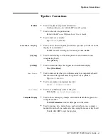
Page 13: ... xii HP 70427A HP 70428A User s Guide Typeface Conventions ...

Page 14: ...tallation Overview 1 2 Standard Equipment Supplied 1 4 Optional Equipment 1 5 Table 1 1 Optional Equipment 1 5 Front Panel 1 6 Connector Saver Installation 1 6 Rear Panel 1 8 Preliminary Work 1 9 Line Voltage 1 9 Verify MMS is Functioning Properly 1 9 Set MS IB Address if Necessary 1 9 Mainframe Assembly 1 10 Install Unit 1 10 1 10 Connect Cables 1 11 Verification 1 12 Procedure A HP 70428A Option...

Page 15: ... 22 To Control the Downconverter over the HP IB IEEE 488 2 2 23 To Configure the Downconverter as a Microwave Source 2 25 HP 70428A Microwave Source Module Overview 2 26 To Access the Source Screen 2 27 To read error messages 2 29 Procedure 2 29 To Output a Signal with a Microwave Source 2 31 Procedure 2 31 To Electrically Tune the Source s Frequency 2 33 Procedure 2 33 To Select Reference Chain P...

Page 16: ...m Control 3 21 Millimeter Phase Noise Measurement System Control 3 25 Overview 3 25 AM Noise Measurement Input AM Detector System Control 3 30 Overview 3 30 Procedure 3 30 AM Noise Measurement IF AM Detector System Control 3 34 Overview 3 34 Spectrum Analyzer Connection User Control 3 38 Overview 3 38 Procedure 3 39 Spectrum Analyzer Connection System Control 3 40 Overview 3 40 Procedure 3 41 3 41...

Page 17: ... 5 Enabling the Status Byte 7 6 Register and Queue Contents 7 7 Table 7 1 Operational Status Register Staus Bit 7 7 7 Table 7 2 Standard Event Status Register Status Bit 5 7 8 Table 7 3 Questionable Status Register Status Bit 3 7 9 Table 7 4 Calibration Status Register 7 10 Remote setup procedure 7 11 Sample HP IB programs 7 12 HP 70428A Microwave Source program example 7 13 Microwave Source Progr...

Page 18: ...paired after April 2014 9 6 Table 9 3 HP 70427A Configuration 3 600 MHz Free running Oscillator 9 7 Table 9 3 Table 9 3A HP 70427A Configuration 3 600 MHz Free running Oscillator Units repaired after April 2014 9 8 Table 9 4 HP 70427A Mixing Spurious 9 10 Table 9 5 HP 70427A AM Detector Noise Floor Specifications 15 dBm 9 11 HP 70427A Microwave Source 9 12 Table 9 6 HP 70427A Source Configuration ...

Page 19: ...0 Table 9 12 Table 9 12A HP 70427A Configuration 3 600 MHz Free running Oscillator Units repaired after April 2014 9 31 Table 9 13 HP 70428A AM Detector Noise Floor Specifications 10 dBm 9 32 HP 70428A Option 002 Specifications 9 34 Table 9 14 HP 70428A Option 002 Configuration 1 All Oscillators Locked 9 35 Table 9 15 HP 70428A Opt 002 AM Detector Noise Floor Specifications 10 dBm 9 37 Table 9 16 ...

Page 20: ...TO IF GAIN 10 34 AUTO RANGE 10 35 BEGIN 10 36 BIAS ON OFF 10 37 BLOCK 10 38 Block 10 39 Data 10 40 Det 10 41 Down Convert 10 42 EXIT 10 43 FREQ 10 44 Freq 10 45 Frequency 10 46 Freqs 10 47 Hardware Control 10 48 HP 437A B 10 49 HP 8662A 10 50 HP 8663A 10 51 HP 70100A 10 52 HP IB Addr 10 53 HP IB ADDRESS 10 54 IF 10 55 IF AM NOISE 10 57 IF AM Output 10 58 IF GAIN 10 59 IF Gain 10 60 IF LEVEL 10 61 ...

Page 21: ...IXER BIAS 10 85 Mixer Low Power 10 86 Mixer Max Level 10 87 MIXER MAX LVL 10 88 mm Band 10 89 mm LO 10 90 mm Mixer Bias 10 91 MODE μW mm 10 92 model nr 10 93 Mux 10 94 Optimum Range 10 95 Options 10 96 OTHER 10 97 Output 10 98 Output 10 99 OUTPUT dBm mW 10 100 OUTPUT FREQ 10 101 Output Power 10 102 OUTPUT POWER 10 103 POWER 10 104 Power 10 105 Power 10 106 Power Control 10 107 Power Meter 10 108 P...

Page 22: ...R 10 135 W band 75 100 10 136 YTF 1 Freq 10 137 YTF 2 Freq 10 138 YTF 1 Power 10 139 YTF 2 Power 10 140 YTF Cal 10 141 11 Connectors and Indicators Front and Rear Panel Overview 11 1 Front Panel 11 2 ACT indicator 11 3 AM NOISE output 11 4 Characteristics 11 4 Operating Considerations 11 4 ERR indicator 11 6 Operating considerations 11 6 HP 8662A input 11 7 Limits 11 7 Characteristics 11 7 Operati...

Page 23: ...aracteristics 11 21 Operating considerations 11 21 mW LO output source 11 22 Limits 11 22 Characteristics 11 22 Operating Considerations 11 22 Rear Panel 11 23 10 MHz IN 11 24 Limits 11 24 Characteristics 11 24 Operating considerations 11 24 10 MHz OVEN OUT 11 25 Characteristics 11 25 Operating considerations 11 25 100 MHz OUT 2 dBm 11 26 Characteristics 11 26 Operating considerations 11 26 100 MH...

Page 24: ...ve LO COMMANDS 12 11 Table 12 11 STATUS REPORTING COMMANDS 12 12 13 Block Diagram General Theory of Operation Microwave Deck Assemblies 13 1 General Theory of Operation 600 MHz Reference Chain 13 2 Overview 13 2 Table 13 1 1 The 600 MHz loop locked to the 100 MHz loop with the 100 MHz loop locked to the 10 MHz timebase tuning sensitivity 0 05 ppm V 13 3 Table 13 2 2 The 600 MHz loop locked to the ...

Page 25: ...opt 002 Microwave Deck Assembly 13 38 Overview 13 38 Looking at the Block Diagram 13 38 Table 13 18 Standard Frequency Algorithm 13 40 Table 13 19 Low noise High Spur Frequency Algorithm 13 43 HP 70427A Microwave Deck Assembly 13 50 Overview 13 50 Looking at the Block Diagram 13 50 Table 13 20 Downconverter Frequency Algorithm 13 52 HP 70427A Intermediate Frequency IF Amplifier 13 55 Overview 13 5...

Page 26: ...e 14 25 Table 14 10 Spec Lines AM Noise of Source Test 3 14 26 Table 14 11 Result Table Test 3 14 30 Test 4 Comb line Spurs mW LO 14 32 Overview 14 32 Procedure 14 32 Table 14 12 Spur Frequencies Level Results 14 34 Test 5 Mixer Linearity IF 14 35 Overview 14 35 Procedure 14 36 Table 14 13 Mixer Non Linearity 14 37 Table 14 14 Mixer Linearity Results Table 14 38 Test 6 Phase Noise and Spurs of Dow...

Page 27: ...rs 14 80 Table 14 31 Mixer Linearity 14 80 Table 14 32 Phase Noise and Spurs Downconverter 14 81 Table 14 33 Am Detector Noise Floor 14 83 Table 14 34 HP 70428 002 05ppm V Tuning 14 84 Table 14 35 HP 70428A 002 05ppm V Tuning 14 85 Table 14 36 AM Noise And Spurs 14 86 14 86 14 86 15 Adjustments Introduction 15 1 Check RF Source type and address 15 1 Frequency Cal 15 2 Power Cal 15 2 Option 002 Fre...

Page 28: ...n a mainframe or configured into multi instrument workstations including Example A In a stand alone mainframe The modules may also be ordered already installed in a stand alone mainframe HP 71707A HP 71708A and HP 71708A Option 002 Does not require HP IB or MS IB Figure 1 1 Installed in a Stand Alone Mainframe Example B In a mainframe with no display linked to a computer via HP IB Requires HP IB F...

Page 29: ...g of this book Thoroughly read the connector care booklet enclosed to ensure proper care of the connectors Installation Overview The installation procedure for the HP 7042X varies depending on the selected configuration It may include one or more of the following major steps 1 Front and rear panel connector installation installing connector savers 50 ohm terminations and type N to SMA adapter if n...

Page 30: ...70428A User s Guide 1 3 Installation 5 Software configuration entering the appropriate soft and hard key configurations For MMS information beyond what is included in this manual refer to the appropriate MMS manual ...

Page 31: ...ticular module Refer to the MMS manual to identify additional parts included with the MMS Mainframe Before you begin installation Verify that all parts are present and inspect for damage If a part is missing or damaged contact your nearest Hewlett Packard Sales or Service Office Figure 1 4 Standard HP Equipment Supplied with the Module ...

Page 32: ...1 Optional Equipment HP 7042 7A HP 70428A HP 70428A Option 002 Option 915 Service Manuals On a dis k 70427 90003 70428 90007 70428 90008 1 1 1 1 1 HP 70428 K03 Special Option HP 70428 K01 HP 70427A K02 HP 3048A K21 Service Tools and Accessory Kit Tune Voltage Supply Balun Filter ...

Page 33: ...ectors is essential to proper performance See Microwave Connector Care Manual part number 08510 90064 for complete instructions HP 70427A 1 Connect item A 3 5 APC connector savers to Microwave LO Signal Input and RF Analyzer Output 2 Connect item B type N to SMA adapter to IF output 3 Connect item C 50 ohm termination to type N to SMA adapter Figure 1 5 HP 70427A Connector Installation ...

Page 34: ...HP 70428A Connect item A 3 5 APC connector saver to Microwave LO Output Figure 1 6 HP 70428A Connector Installation HP 70428A Option 002 Connect item A 3 5 APC connector savers to Microwave LO Output RF Output Figure 1 7 HP 70428A Option 002 Connector Installation ...

Page 35: ...m terminations for the rear panel are the same for each of the HP 70427A HP 70428A and HP 70428A Option 002 1 Connect item C to Buffered 10 MHz Out 100 MHz Out 8 dBm 600 MHz Out 20 dBm 2 Connect item D to 600 MHz Out 0 dBm 3 Connect item E to 100 MHz Out 2 dBm Figure 1 8 50 OHM Terminations Installation Connection ...

Page 36: ...ble 2 The address map should be accessible and show all the currently configured modules in their correct locations 3 Note the location of all modules in Row 0 4 There should be no errors present If the mainframe does not appear to be functioning properly consult the MMS manual for troubleshooting before continuing with the installation procedure Set MS IB Address if Necessary If your module will ...

Page 37: ...allation Mainframe Assembly Mainframe Assembly Install Unit 1 Slide the Unit into the mainframe Figure 1 9 Unit Installation 2 Tighten the bolt using the 8 mm hex ball driver Then close lid Figure 1 10 Tightening Bolt using 8 mm Hex Ball Driver ...

Page 38: ...r up Verify that the unit is working a Six LED s on the front panel will illuminate for about six seconds then blink off b Screen should have a display which will vary depending upon the state of the instrument the last time it was used c Only ACT LED should remain lit on the active instrument If the other LED s stay on an error is present see chapter 2 Getting Started for help reading error messa...

Page 39: ...eration Enter a test frequency of 10 GHz to verify that the module responds to the mms display HP 70427A Verification 1 Press The Freqs softkey Figure 1 12 Freqs Softkey Location 2 Press the INPUT FREQ softkey Figure 1 13 INPUT FREQ Softkey Location 3 Enter 10 with the numeric keypad 4 Then press the GHz softkey ...

Page 40: ...e 1 14 GHz Softkey Location The module will display standby tuning for a few seconds then it will display the output frequency HP 70428A Verification 1 Press the Output softkey Figure 1 15 Output Softkey Location 2 Press the FREQ softkey Figure 1 16 FREQ Softkey Location ...

Page 41: ... 1 Press the Source softkey Figure 1 18 Source Softkey Location 2 Follow the instructions for standard HP 70428A verification If you are installing an HP 70428A Option 002 using an HP 8662A or HP 8663A additional softkey configurations are necessary See procedure A at the end of this chapter If you are installing an HP 70427A or HP 70428A into a mainframe with a display installation is complete CA...

Page 42: ...662A HP 8663A Procedure A HP 70428A Option 002 using HP 8662A HP 8663A Softkey Configuration Procedure 1 Press the Service softkey Figure 1 19 Service Softkey Location 2 Press the Misc softkey Figure 1 20 Misc Softkey Location 3 Press the RF Source Softkey Figure 1 21 RF Source Softkey Location ...

Page 43: ...on 002 using HP 8662A HP 8663A 4 Press the HP 8662 or HP 8663A softkey Figure 1 22 HP 8662 or HP 8663A Softkey Location Press the HP IB ADDRESS softkey The enter HP IB Address Figure 1 23 HP IB ADDRESS Softkey Location 5 Press the Enter softkey Figure 1 24 ENTER Softkey Location ...

Page 44: ...HP 70427A HP 70428A User s Guide 1 17 Installation Procedure A HP 70428A Option 002 using HP 8662A HP 8663A 6 Press the Output softkey Figure 1 25 Output Softkey Location Installation is now complete ...

Page 45: ... available address locations If you need to change the HP IB address there are two ways to proceed I You may temporarily change the HP IB address using softkey configurations described in the HP mms mainframe Operation Guide or II You may change the MS IB address switches which will also change the HP IB default address This procedure is described below 1 The MS IB row switches for the HP 70427A H...

Page 46: ... Started Overview This chapter contains basic operating instructions for the HP 70427A Downconverter HP 70428A Microwave Source and the HP 70428A Option 002 Microwave Source tunable source Figure 2 1 Models HP 70427A HP 70428A HP 70428A Option 002 ...

Page 47: ...tween 300 and 900 MHz The input signal goes from the SIGNAL connector to a 0 to 35 dB step attenuator 5 dB steps before being mixed with the LO An adjustable IF amplifier follows the mixer It s gain range is 10 to 45 dB in 5 dB steps For input frequencies below 1 5 GHz the signal goes through the input attenuator and to the IF amplifier bypassing the mixer Detecting AM noise at the RF input The do...

Page 48: ...ttenuator and to the RF ANALYZER connector Monitoring the IF output When the VIEW IN IF softkey has IF underlined a portion of the IF amplifier s output is routed to the IF connector and to the RF ANALYZER connector so that the IF signal can be monitored while the downconverter operates normally Configuring the reference chain The downconverter s local oscillator LO is derived from a low noise ref...

Page 49: ... harmonics internally One of these harmonics mixes with the input signal to produce an IF between 5 MHz and 1 2 GHz Using the HP 70427A as a Microwave source The HP 70427A includes the functions of the HP 70428A Microwave Source When the module is used as a downconverter the source hardware functions as the internal local oscillator LO When the Source softkey is pressed the microwave source screen...

Page 50: ...Look at the ACT indicator on the HP 70427A s front panel If it is lit the module is active and can be controlled by the MMS display If it is not lit do the following 1 Press the DISPLAY key 2 Press the NEXT INSTR softkey until the HP 70427A s ACT indicator lights If the MMS display is connected to more than one module a different module will become the active module each time the NEXT INSTR softke...

Page 51: ...2 6 HP 70427A HP 70428A User s Guide Getting Started To Access the Downconverter Screen Step 2 Display the downconverter screen 1 Press the INSTR PRESET key Figure 2 5 Downconverter Display ...

Page 52: ... indicator lights when an error occurs Step 1 Access the error message screen 1 Press the DISPLAY key 2 Press the REPORT ERRORS softkey Figure 2 6 Message Error Access Step 2 Look up the error messages Error messages are described in the Messages section in the back of this manual Figure 2 7 Error Message Manual Sample ...

Page 53: ...Started To read error messages Step 3 Clear the messages Press the REPORT ERRORS softkey repeatedly until No Errors is displayed If the condition that caused the error still exists the error message will re appear Figure 2 8 Report Errors Softkey ...

Page 54: ...ic keys 3 Complete the entry by pressing the appropriate units softkey GHz MHz kHz or Hz Figure 2 9 Input Frequency Screen Diagram The module s firmware will calculate and display the IF and LO frequencies and tune the YIG Tuned Filter YTF Tuning can take up to 4 seconds Step 2 Adjust the mixer input level if necessary 1 Press the Amplitudes softkey 2 Press the more 1 of 2 softkey 3 Press the INPU...

Page 55: ...nput to the mixer must not exceed 10 dBm For Diagram if the input signal is 25 dBm there must be at least 15 dB of input attenuation The optimum level is between 10 dBm and 5 dBm Another way to adjust the input attenuation is to trigger a one time auto ranging This must be done after a signal is connected see step 3 below Step 3 Connect the cables 1 The signal to be downconverted goes to the input...

Page 56: ...e Amplitudes softkey 2 Press the more 1 of 2 softkey 3 Press the AUTO ATTEN softkey The level set by auto ranging depends on the level shown on the Mix Max Level display This level is set by the MIXER MAX LVL softkey If it is 5 dBm the attenuator will be set so that the mixer input level is within optimum range For input signal levels less than 10 dBm the attenuator must be set manually Step 4 Adj...

Page 57: ... IF Gain Display Diagram To automatically adjust the IF gain Another way to adjust the IF gain is to trigger a one time auto ranging 1 Press the Amplitudes softkey 2 Press the more 1 of 2 softkey 3 Press the AUTO IF GAIN softkey Auto ranging sets the IF gain for an IF output level between 0 dBm and 6 dBm ...

Page 58: ...Bm Step 1 Access the downconverter screen Make sure the downconverter is in microwave mode To do this press the Freqs softkey and look at the MODE μW mm softkey It must have μW underlined Figure 2 13 Downconverter Screen Display Diagram Step 2 Select AM mode 1 Press the AM Noise softkey 2 Press the AM NSE IN IF softkey so that IN is underlined Figure 2 14 Select AM Mode Display Diagram ...

Page 59: ... a signal look at the Input Atten and make sure enough attenuation is inserted so that the input to the detector does not exceed 20 dBm 1 The signal to be detected goes to the input SIGNAL connector 2 The demodulated signal is taken from the AM NOISE output connector This output is AC coupled Figure 2 15 Connect Cables Diagram ...

Page 60: ...n 5 dB steps with the numeric keypad 3 Press the dB softkey to complete the entry Figure 2 16 Detector Input Level Display Diagram Enough attenuation should be used to keep the detector s input below 20 dBm The optimum range is 10 to 15 dBm To Automatically Adjust the Input Attenuation Another way to adjust the input attenuation is to trigger a one time auto ranging To do this press the AUTO ATTEN...

Page 61: ...e signal path when the downconverter is downconverting signals It can be used in mm mode and μW mode that is the MODE μW mm softkey can have either μW or mm underlined Make sure the AM noise mode is set to IF To do this press the AM Noise softkey and look at the AM NSE IN IF softkey It must have IF underlined Figure 2 17 AM IF AM Display Diagram ...

Page 62: ... IF AM Detector Step 1 Set up the downconverter to downconvert a signal 1 Enter the input frequency 2 Set input attenuation and or IF gain if necessary 3 Connect the signal to be downconverted and demodulated to the SIGNAL connector Figure 2 18 Downconverter Signal Setup ...

Page 63: ...nalyzed with a low frequency spectrum analyzer The IF LEVEL output is DC coupled and filtered Its signal is a DC analog of the downconverter s IF level 1 Press the Amplitudes softkey 2 Press the more 1 of 2 softkey 3 Press the IF AM Output softkey 4 Select the output by pressing one of the following softkeys The IF AM NOISE softkey selects the AM NOISE connector The IF LEVEL softkey selects the IF...

Page 64: ...ically Tune the Downconverter s LO To Electrically Tune the Downconverter s LO Step 1 Select the tuning sensitivity 1 Press the Ref Chain softkey 2 Press the Tune Sens softkey 3 Press the 05 ppm v 1 0 ppm v or 20 ppm v softkey Figure 2 20 Tuning Sensitivity Diagram ...

Page 65: ...Hz oscillator which is phase locked to the 10 MHz oscillator In this configuration a 1 Volt tuning voltage will cause a 0 05 ppm change in the downconverter s LO frequency Tuning with a Sensitivity of 1 0 ppm V With a tuning sensitivity of 1 0 ppm V the reference chain s 100 MHz oscillator is tuned and the 600 MHz oscillator is phase locked to it A 1 Volt tuning voltage will cause a 1 ppm change i...

Page 66: ...width Step 1 Determine the tuning sensitivity setting 1 Press the Ref Chain softkey 2 Press the Tune Sens softkey 3 Note which sensitivity on the right side of the screen is underlined Figure 2 22 Reference Chain Phase Lock Loop Bandwidth Diagram The 100 MHz and or 600 MHz phase lock loop bandwidths can be set depending on the tuning sensitivity See the following table ...

Page 67: ...he softkey that corresponds to the desired bandwidth Figure 2 23 Tuning the Sensitivity Setting Diagram Table 2 1 The 100 MHz and or the 600 MHz Phase Lock Loop Bandwidths and Tuning Sensitivity Tuning Sensitivity Bandwidth Settings 0 ppm 100 MHz and or 600 MHz phase lock loops 0 05 ppm V 100 MHz and or 600 MHz phase lock loops 0 1 ppm V 600 MHz phase lock loop 20 ppm V None 100 MHz no tune 600 MH...

Page 68: ... be displayed The two last two digits after the comma are the last two digits of the address Figure 2 24 HP IB Address Location Diagram For example an HP 70724A with address 28 would display HP 70427A 0 28 The complete HP IB address for a computer with its HP IB interface select code set to seven would be 728 If the downconverter doesn t respond to this address look on the MMS address map to see i...

Page 69: ...MMS mainframe that the downconverter is installed in Figure 2 25 HP IB Connection Diagram Step 3 Enter a program and run it The following Diagram is for the HP BASIC on a HP 9000 series 200 300 controller It sets the downconverter s frequency input attenuation and IF level Chapter 12 has a complete table of HP IB commands Figure 2 26 HP BASIC on an HP 9000 series 200 300 Controller ...

Page 70: ...ave Source To Configure the Downconverter as a Microwave Source 1 Press the source softkey The HP 70428A menus and screens will be displayed Follow the operating instructions for the source Frequency and amplitude settings are preserved in the source and downconverter when switching back and forth ...

Page 71: ...r which can be the reference or it can be phased locked to a 10 MHz crystal controlled reference The reference chain s tuning sensitivity and phase lock loop bandwidths can be selected from menus on the MMS display A voltage applied to the VOLTAGE CONTROL connector can tune the reference chain A step recovery diode multiplies the 600 MHz and a YIG tuned filter YTF picks off the desired frequency T...

Page 72: ...CT indicator on the HP 70428A s front panel If it is lit the module is active and can be controlled by the MMS display If it is not lit do the following 1 Press the DISPLAY key 2 Press the NEXT INSTR softkey until the HP 70428A s ACT indicator lights If the MMS display is connected to more than one module a different module will become the active module each time the NEXT INSTR softkey is pressed ...

Page 73: ...o Access the Source Screen Step 2 Display the Source Screen Press the INSTR PRESET key if the module is an HP 70427A or HP 70428A Option 002 access the source screen by pressing the source softkey Figure 2 29 HP 70427A and HP 70428A Option 002 Source Screen ...

Page 74: ...ator lights when an error occurs Procedure Step 1 Access the error message screen 1 Press the DISPLAY key 2 Press the REPORT ERRORS softkey Figure 2 30 Message Error Access Step 2 Look up the error messages Error messages are described in the Messages section in the back of this manual Figure 2 31 Error Message Manual Sample ...

Page 75: ...Started To read error messages Step 3 Clear the messages Press the REPORT ERRORS softkey repeatedly until No Errors is displayed If the condition that caused the error still exists the error message will re appear Figure 2 32 Report Errors Softkey ...

Page 76: ...softkey 2 Press the FREQ softkey 3 Key in a frequency between 2 4 GHz and 26 4 GHz with the numeric keypad 4 Complete the entry by pressing the appropriate units softkey The module s firmware will round off the entered frequency to the nearest 600 MHz It will ignore frequencies outside the above range The firmware will also set the power to 0 dBm Figure 2 33 Microwave Source Signal Softkeys Locati...

Page 77: ...l be accepted 1 Press the OUTPUT POWER softkey 2 Press the POWER softkey 3 Key in the output power dBm or mW with the numeric keypad Power levels between 0 and 20 100 mW in 0 1 dB steps can be entered But the minimum specified power is shown below 2 4 to 6 6 GHz 16 7 2 to 25 8 GHz 10 Also the actual resolution can be as much as 0 2 dB 4 Press the dBm or mW softkey Figure 2 34 Output Power Softkey ...

Page 78: ... the Source s Frequency To Electrically Tune the Source s Frequency Procedure Step 1 Select the tuning sensitivity 1 Press the Ref Chain softkey 2 Press the Tune Sens softkey 3 Press the 0 05 ppm V 1 0 ppm V or 2 0 ppm V softkey Figure 2 35 Electrically Tune Source s Softkeys ...

Page 79: ...oscillator which is phase locked to the 10 MHz oscillator In this configuration a 1 Volt tuning voltage will cause a 0 05 ppm change in the tunable source s output frequency Tuning with a Sensitivity of 1 0 ppm V With a tuning sensitivity of 1 0 ppm V the reference chain s 100 MHz oscillator is tuned and the 600 MHz oscillator is phase locked to it A 1 Volt tuning voltage will cause a 1 ppm change...

Page 80: ...ettings 1 Press the REF Chain softkey 2 Press the Tune Sens softkey 3 Note which sensitivity on the right side of the screen is underlined Figure 2 37 Tuning Sensitivity Softkey Locations The 100 MHz and or 600 MHz bandwidth can be set depending on the tuning sensitivity Tuning Sensitivity Bandwidth can be set for 0 ppm 100 MHz and or 600 MHz phase lock loops 0 5 ppm V 100 MHz and or 600 MHz phase...

Page 81: ...V 600 MHz phase lock loop 20 ppm V None 100 MHz no tune 600 MHz phase lock loop 600 MHz no tune None Step 2 Select the bandwidth 1 Press the Ref Chain softkey 2 Press either 100 MHz PLL BW or 600 MHz PLL BW softkey 3 Press the softkey that corresponds to the desired bandwidth Figure 2 38 Bandwidth Softkey Locations ...

Page 82: ...ses should be displayed The two digits after the coma are the last two digits of the address Figure 2 39 HP IB Address Location For example an HP 70428A with address 28 would display HP 70428A 0 28 The complete HP IB address for a computer with its HP IB interface select code set to seven would be 728 If the source doesn t respond to this address look on the MMS address map to see if it has change...

Page 83: ...e computer to the MMS mainframe that the source is installed in Figure 2 40 HP IB Cable Connection Step 3 Enter a program and run it The following is for HP BASIC on an HP 9000 series 200 300 controller It sets the source s frequency and output power Chapter 12 has a complete table of HP IB commands Figure 2 41 HP BASIC on a HP 9000 Series 200 300 Controller ...

Page 84: ...Tunable Source Overview The HP 70428A Option 002 Microwave Source Module Tunable Source up converts and HP 8662 3A signal generator s output into the 2 4 GHz to 26 5 GHz range It consists of a microwave source as described in the previous section and a mixer with a second YIG tuned filter Figure 2 42 HP 70428A Option 002 ...

Page 85: ...ule Look at the ACT indicator on the HP 70428A Option 002 s front panel If it is lit the module is active and can be controlled by the MMS display If it is not lit do the following 1 Press the DISPLAY key 2 Press the NEXT INSTR softkey until the HP 70428A Option 002 s ACT indicator lights If the MMS is connected to more than one module a different module will become the active module each time the...

Page 86: ...HP 70427A HP 70428A User s Guide 2 41 Getting Started To Access the Tunable Source Screen Step 2 Display the tunable source 1 Press the INSTR PRESET key Figure 2 44 INSTR PRESET key location ...

Page 87: ...ator lights when an error occurs Procedure Step 1 Access the error message screen 1 Press the DISPLAY key 2 Press the REPORT ERRORS softkey Figure 2 45 Message Error Access Step 2 Look up the error messages Error messages are described in the Messages section in the back of this manual Figure 2 46 Error Message Manual Sample ...

Page 88: ...Started To read error messages Step 3 Clear the messages Press the REPORT ERRORS softkey repeatedly until No Errors is displayed If the condition that caused the error still exists the error message will re appear Figure 2 47 Report Errors Softkey ...

Page 89: ...HP 70428A Option 002 Procedure Step 1 Connect the Signal Generator Figure 2 48 Signal Generator Connection 1 Connect an HP IB cable between the signal generator and the MMS mainframe that the HP 70428A Option 002 is installed in 2 Connect an RF cable between the signal generator s RF OUTPUT connector and the HP 70428A Option 002 s HP 8662A connector NOTE The HP 70428A Option 002 acts as a controll...

Page 90: ...a Signal with the Tunable Source Step 2 Select the signal generator type 1 Press the Service softkey 2 Press the Misc softkey 3 Press the RF Source softkey 4 Press the HP 8662A or HP 8663A softkey 5 Press the EXIT softkey Figure 2 49 Signal Generator Type Selection ...

Page 91: ...a Signal with the Tunable Source Step 3 Enter the generator s HP IB address 1 Press the HP IB ADDRESS softkey 2 Enter the signal generator s HP IB address with the numeric keypad 3 Press the ENTER softkey to complete the entry Figure 2 50 HP IB Address Key Locations ...

Page 92: ...unable Source Step 4 Enter the output frequency 1 Press the Output softkey 2 Press the OUTPUT FREQ softkey 3 Key in a frequency between 2 4 GHz and 26 5 GHz with the numeric keyboard 4 Press the GHz MHz or Hz softkey to complete the entry Figure 2 51 Output Frequency Softkey Locations ...

Page 93: ... softkey 2 Key in the output power with the numeric keypad Power levels between 0 and 20 100 mW in 0 1 dB steps can be entered But the minimum specified power is shown below 2 4 to 6 6 GHz 16 6 6 to 25 8 GHz 10 Also actual resolution can be as much as 0 2 dB 3 Press the dBm or mW softkey to complete the entry Figure 2 52 Output Power Softkey Locations ...

Page 94: ... Tunable Source s Frequency To Electrically Tune the Tunable Source s Frequency Procedure Step 1 Select the tuning sensitivity 1 Press the Ref Chain softkey 2 Press the Tune Sens softkey 3 Press the 0 05 ppm V 1 0 ppm V or 2 0 ppm V softkey Figure 2 53 Electrically Tune Softkeys ...

Page 95: ... MHz oscillator which is phase locked to the 10 MHz oscillator In this configuration a 1 Volt tuning voltage will cause a 0 05 ppm change in the tunable source s output fequency Tuning with a Sensitivity of 1 0 ppm V With a tuning sensitivity of 1 0 ppm V the reference chain s 100 MHz oscillator is tuned and the 600 MHz oscillator is phase locked to it A 1 Volt tuning voltage will cause a 1 ppm ch...

Page 96: ...ress the Tune Sens softkey 3 Note which sensitivity on the right side of the screen is underlined Figure 2 55 Tuning Sensitivity Softkey Locations The 100 MHz and or 600 MHz bandwidth can be set depending on the tuning sensitivity Tuning Sensitivity Bandwidth can be set for 0 ppm 100 MHz and or 600 MHz phase lock loops 0 5 ppm V 100 MHz and or 600MHz phase lock loops 1 0 ppm V 600 MHz phase lock l...

Page 97: ...andwidth 20 ppm V None 100 MHz no tune 600 MHz phase lock loop 600 MHz no tune None Step 2 Select the bandwidth 1 Press the Ref Chain softkey 2 Press either 100 MHz PLL BW or 600 MHz PLL BW softkey 3 Press the softkey that corresponds to the desired bandwidth Figure 2 56 Bandwidth Softkey Locations ...

Page 98: ...ave Source To Configure the Tunable Source as a Microwave Source Procedure 1 Press the Source softkey The HP 70428A menus and screens will be displayed Figure 2 57 Source Softkey Location 2 Frequency and amplitude settings are preserved in the source and tunable source when switching back and forth ...

Page 99: ...2 54 HP 70427A HP 70428A User s Guide Getting Started To Configure the Tunable Source as a Microwave Source ...

Page 100: ... AM Noise Measurement IF AM detector User Control The next for procedures are for system control of the HP 70427A with HP 3048A software versions A 03 00 and later Phase Noise Measurement 26 5 GHZ System Control Millimeter Phase Noise Measurement System Control AM Noise Measurement Input AM detector System Control AM Noise Measurement IF AM detector System Control The final two procedures are for ...

Page 101: ... 5 MHz and 1500 MHz Frequencies below 1 5 GHz bypass the downconverter s mixer and pass through the IF amplifier Figure 3 1 Phase Noise Measurement 26 5 GHz User Control Connection This procedure can be used for all HP 3048A and HP 3047A software versions The HP 70427A is controlled manually The HP 70427A noise specifications in chapter 9 of the manual are provided for the HP 70427A alone and comb...

Page 102: ...ypad 4 Press the GHz MHz kHz or Hz softkey 5 Read the IF frequency from the IF display Step 3 Decide which instrument to tune There are three choices for phase locking by using either the DUT the reference source or for frequencies 1 5 GHz the downconverter s LO can be turned Tuning the HP 8662A 3A If the DUT is referenced to an oven stabilized oscillator the HP 8662A 3A can be tuned Connect the t...

Page 103: ...eded The only reason to use anything other than the default bandwidth is if the downconverter is being tuned using the ppm V tuning sensitivity and the HP 3048A system PLL bandwidth is greater than 10 kHz If the downconverter is being tuned its phase lock loop bandwidth must be wider than the HP 3048A system bandwidth If it isn t the system software can t accurately compensate for loop suppression...

Page 104: ...stant unless the HP 8662 3A is being tuned with the DC FM then it should be computed The Computed PLL Suppression WILL be verified 4 Specify the control of Signal Sources Downconverter USER S DEVICE MANUAL CONTROL Tune Voltage Select the instrument that will be tuned unless the downconverter is being tuned If the downconverter is being tuned select one of the sources With phase noise using a phase...

Page 105: ...e autoranging of the downconverter s input attenuator and IF gain Step 9 Verify beatnote and proceed If the reference source is under user control adjust the frequency if necessary to get a beatnote less than 5 of the peak tune range VCO Tuning Constant Voltage Tuning Range of VCO If the reference source is under system control it will be tuned automatically After the beatnote is within the limits...

Page 106: ...ut between 5 MHz and 1200 MHz The downconverter supplies the external harmonic mixer with mixer bias current and a 2 4 GHz to 6 GHz signal which the harmonic mixer multiplies internally to produce the mm LO Figure 3 2 Millimeter Phase Noise Measurement User Control Connection Refer to Hewlett Packard Application Note 385 for information on making millimeter phase noise measurements and to the harm...

Page 107: ... 4 Press the EXIT softkey Step 3 Determine the downconverter s IF frequency The downconverter s IF frequency will be displayed on the IF display The downconverter calculates this frequency when an input frequency is entered In mm mode the input frequency must be in the mm band selected in step 2 First enter the DUT frequency into the downconverter as follows 1 Press the Freqs softkey 2 Press the I...

Page 108: ...g sensitivity can be selected so that its tuning range will be greater than the expected drift of the DUT The choices are 1 0 ppm V 600 MHZ PLL bandwidth must be greater than the HP 3048A PLL bandwidth 20 ppm V Tuning the DUT Refer to the Signal Source Applications chapter of the HP 3048A manual for information on tuning the DUT Step 6 Select the downconverter s tuning sensitivity Do this only if ...

Page 109: ...0427A LO frequency Tuning Sensitivity HP 8662A 3A EFC 10 8 Downconverter IF frequency DC FM peak deviation Center Voltage of VCO Tuning Curve HP 70427A 0 V HP 8662A 3A 0 V EFC and DC FM Voltage Tuning Range of VCO HP 70427A 5 V HP 8662A 3A 10 V EFC and DC FM VCO Tune port Input Resistance HP 70427A 1 MΩ HP 8662A 3A EFC 1MΩ DC FM 1kΩ HP 8662A 600 Ω HP 8663A Phase Detector Internal Phase Detector 5 ...

Page 110: ... mixer bias if necessary If mixer bias was enabled in step 4 adjust the mixer bias current for maximum signal level from the harmonic mixer as measured at the downconverter s IF output 1 Connect a spectrum analyzer to monitor the downconverter s IF a Connect a spectrum analyzer to monitor the downconverter s RF ANALYZER output b Press the Amplitudes softkey c Press the VIEW IN IF softkey until IF ...

Page 111: ... the mixer bias adjustment 5 Autorange the downconverter s IF gain as follows a Press the Amplitudes softkey b Press the AUTO RANGE softkey Step 11 Verify the beatnote and proceed If the reference source is under the user control adjust its frequency if necessary to get a beatnote less than 5 of peak tuning range If the reference source is under system control it will be tuned automatically After ...

Page 112: ...47A Phase Noise measurement software The HP 70427A is controlled manually With HP 3048A software versions A 03 00 or later the HP 70427A can be controlled by the software Procedure Figure 3 3 AM Noise Measurement Input AM Detector User Control Connection Step 1 Preset the Converter First make sure the downconverter s ACT indicator light is lit If it isn t do the following a Press the DISPLAY key b...

Page 113: ...l Phase AM Detector 3 Specify a Calibration Process Phase Detector Constant Derive from Double Sided Spur Spur Amplitude 26 dBc Spur Frequency 1kHz 4 Specify the Control of Signal Sources CAL sources USERS DEVICE MANUAL CONTROL Step 4 Begin a new measurement When the HP 3048A software pauses at the system connect diagram connect the DUT to the downconverter s SIGNAL input and make any other connec...

Page 114: ...quency is 500 MHz Use the DUT frequency IF DUT frequency is 500 MHz Use the 500 MHz if the cal source can tune the DUT frequency use the DUT frequency Power 10 dBm Modulation OFF Now adjust the calibration source power so that the voltage measured at the output of the AM detector is within 5 of what it was with the DUT connected to the downconverter 1 Read the AM Det Voltage display 2 Press the RE...

Page 115: ...ser s Guide Downconverter Operation AM Noise Measurement Input AM Detector User Control Frequency 1 kHz Step 10 Proceed with the measurement Re connect the DUT to the downconverter s SIGNAL input and proceed with the measurement ...

Page 116: ...n be measured The RF AM detector is limited to carrier levels greater than 0 dBm With the IF Am detector carrier levels down to 30 dBm can be measured because the signal is amplified by the IF amplifier before going to the IF Am detector The IF AM detector can also be used with the downconverter in mm mode external harmonic mixer To do this set up the downconverter for downconverting a mm wave sig...

Page 117: ... Press the GHz MHz kHz or Hz softkey Step 3 Enable the IF AM detector 1 Press the AM Noise softkey 2 Press the AM NSE IN IF softkey until the IF is underlined 3 Press the Freqs softkey Step 4 Define the measurement Follow the instructions in the HP 3048A manual together with the information below 1 Specify Measurement Type and Frequency Range Measurement Type AM Noise 2 Enter Source and Interface ...

Page 118: ...er s internal voltmeter 1 Press the AM Noise softkey 2 Read the AM Det Voltage display 3 Press the READ AM DET softkey 4 Press the READ AM DET softkey again 5 Repeat from step 1 above until the reading on the AM DET Voltage display doesn t change from one reading to the next 6 Record the final reading for use in the following step Step 8 Measure and adjust the calibration source power Connect the ...

Page 119: ...utput power 6 Repeat steps 1 through 4 to read the detector s output at the new power 7 Repeat steps 1 through 5 until the calibration source s detector voltage is within 5 of the DUT s detector voltage Step 9 Run the calibration Modulate the calibration source as follows Type AM Depth 10 Frequency 1 kHz Step 10 Proceed with the measurement Re connect the DUT to the downconverter s SIGNAL input re...

Page 120: ...converter s mixer and pass through the IF amplifier This procedure can be used for all HP 3048A software versions A 03 00 or later The software can be configured for system control of the HP 70427A With earlier versions of the software the HP 70427A must be controlled manually Figure 3 5 Phase Noise Measurement 26 5 GHz System Control Connection The HP 70427A noise specifications in chapter 9 of t...

Page 121: ...rter s LO should be tuned The downconverter s tuning sensitivity can be selected so that it s tuning range will be greater than the expected drift of the DUT The choices are 1 0 ppm V 600 MHz PLL bandwidth must be greater than the HP 3048A PLL bandwidth 20 ppm V Noise performance depends on tuning sensitivity so it may be necessary to trade off noise performance for tuning range Refer to a specifi...

Page 122: ...662A 3A 10 V EFC and DC FM VCO Tune port Input Resistance HP 70427A 1MΩ HP 8662A 3A EFC1MΩ HP 8662A DC FM 1kΩ HP 8663A DC FM 600Ω Phase Detector Internal Phase Detector 5 MHz to 1600 MHz 4 Specify a Calibration Process Determining PHASE DETECTOR CONSTANT Measure the Detector Constant Determining the VCO TUNING CONSTANT Measure the VCO Tuning Constant unless the HP 8662A 3A is being tuned with the ...

Page 123: ...he HP 3048A PLL bandwidth see step 1 The only reason to use anything other than the default bandwidth is if the downconverter is being tuned using 1 0 ppm V tuning sensitivity and the HP 3048A system bandwidth is greater than 10 kHz If the downconverter is being tuned the 600 MHz PLL bandwidth must be wider than the HP 3048A system bandwidth Step 3 Start a new measurement Connect the sources when ...

Page 124: ...s SIGNAL input between 5 MHz and 1200 MHz The downconverter supplies the external harmonic mixer with mixer bias current and a 2 4 GHz to 6 GHz signal which the harmonic mixer multiplies internally to produce the mm LO Figure 3 6 Millimeter Phase Noise Measurement System Control Connection Refer to Hewlett Packard Application Note 385 for information on making millimeter phase noise measurements a...

Page 125: ... tuned The downconverter s tuning sensitivity can be selected so that it s tuning range will be greater than the expected drift of the DUT The choices are 1 0 ppm V 600 MHz PLL bandwidth must be greater than the HP 3048A PLL bandwidth 20 ppm V Noise performance depends on tuning sensitivity so it may be necessary to trade off noise performance for tuning range Refer to a specification table in cha...

Page 126: ...HP 70427A 0 V HP 8662A 3A 0 V EFC and DC FM Voltage Tuning Range of VCO HP 70427A 5 V HP 8662A 3A 10 V EFC and DC FM VCO Tune port Input Resistance HP 70427A 1MΩ HP 8662A 3A EFC 1MΩ HP 8662A DC FM 1kΩ HP 8663A DC FM 600Ω Phase Detector Internal Phase Detector 5 MHz to 1600 MHz 4 Specify a Calibration Process Determining PHASE DETECTOR CONSTANT Measure the Detector Constant Determining the VCO TUNI...

Page 127: ...h use the default 126 Hz 600 MHz Ref Chain PLL Bandwidth use the default 10 kHz Unless use of a wider bandwidth is dictated by the tuning sensitivity and the HP 3048A PLL bandwidth see step 1 The only reason to use anything other than the default bandwidth is if the downconverter is being tuned using 1 0 ppm V tuning sensitivity and the HP 3048A system bandwidth is greater than 10 kHz If the downc...

Page 128: ...t below the point where the signal starts being compressed as indicated by the RF spectrum analyzer 4 Adjust mixer bias for a minimum IF signal measured by the spectrum analyzer a Move the cursor to the mm Band Mixer Bias line b Adjust the bias level with the Left Right arrow keys Repeat these steps for maximum IF output measured on the RF spectrum analyzer Step 5 Autorange the downconverter s IF ...

Page 129: ...sions A 03 00 or later The software can be configured for system control of the downconverter Figure 3 7 AM Noise Measurement Input AM Detector System Control Connection Procedure Step 1 Define the Measurement Follow the instructions in the HP 3048A manual together with the information below 1 System Configuration Enter the downconverter in the system configuration table Refer to chapter 1 in this...

Page 130: ...ermined by the system if AUTO is selected AM Detector Maximum Level system enters the default value System Spectrum Analyzer Connection Port HP 11848A Step 2 Begin a new measurement When the HP 3048A software pauses at the system connect diagram connect the DUT to the downconverter s SIGNAL input and make any other connections shown that haven t been done yet Also set the DUT power to 10 dBm The d...

Page 131: ...calibration as follows Frequency IF DUT frequency is 500 MHz Use the DUT frequency IF DUT frequency is 500 MHz Use the 500 MHz if the cal source can tune the DUT frequency use the DUT frequency Power 10 dBm Modulation OFF Adjust the calibration source power so that the voltage measured at the output AM detector is within 5 of what it was with the DUT connected to the downconverter 1 Read the AM DE...

Page 132: ... Measurement Input AM Detector System Control Step 6 Run the calibration Modulate the calibration source as follows Type AM Depth 10 Frequency 1 kHz Step 7 Proceed with the measurement Re connect the DUT to the downconverter s SIGNAL input and proceed with the measurement ...

Page 133: ...t is that a lower power carrier can be measured The RF AM detector is limited to carrier levels greater than 0 dBm With the IF AM detector carrier levels down to 30 dBm can be measured because the signal is amplified by the IF amplifier before going to the IF AM detector The IF AM detector can also be used with the downconverter in mm mode external harmonic mixer To do this set up the downconverte...

Page 134: ...s IF frequency NOTE To find the IF frequency manually enter the carrier frequency into the HP 70427A It will calculate and display the IF frequency Detector HP 70427A IF AM Detector 4 Specify a Calibration Process Phase Detector Constant Derive from Double Sided Spur Spur amplitude 26 dBc Spur frequency 1 kHz 5 Specify the Control of Signal Sources AM Detector 70427A SYSTEM CONTROL CAL source USER...

Page 135: ...ystem connect diagram connect the DUT to the downconverter s SIGNAL input and make any other connections shown that haven t been done yet Step 3 Autorange the downconverter Press the DC Auto Range softkey on the HP 3048A controller This triggers a one time autoranging of the downconverter s input attenuator Step 4 Measure the AM detector s output voltage The detector s output voltage is measured w...

Page 136: ... Repeat from step 1 above until the reading on the AM Det Voltage display doesn t change from one reading to the next 5 If necessary increment decrement the calibration source s output power 6 Repeat steps 1 through 4 above to read the detector s output at the new power 7 Repeat steps 1 through 5 above until the calibration source s detector voltage is within 5 of the DUT s detector voltage Step 6...

Page 137: ...48A connected to the downconverter as shown above the downconverter s input or IF can be routed to the RF spectrum analyzer or the HP 11848A RF analyzer output can be routed to the RF spectrum analyzer This procedure can be used for all HP 3048A software versions The downconverter is controlled manually At the connection diagram the RF spectrum analyzer can be routed to view the HP 3048A beat note...

Page 138: ...downconverter s input signal is routed to the RF spectrum analyzer after it passes through the input attenuator It does not go to the mixer or IF output 2 Press the VIEW IN IF softkey until the IF is underlined a A sample of the downconverter s IF output is routed to the RF spectrum analyzer The downconverter operates normally 3 Press the HP 11848A softkey until the is underlined a The spectrum an...

Page 139: ...rol With the RF spectrum analyzer and the HP 11848A connected to the downconverter as shown above the downconverter s input or IF can be routed to the RF spectrum analyzer or the HP 11848A can be routed to the RF spectrum analyzer This procedure can be used for HP 3048A software versions A 03 00 The software can be configured for system control of the downconverter NOTE This procedure assumes that...

Page 140: ...pauses at the connect diagram access the HP 70472 PARAMETERS screen by pressing the 70427A Parms softkey 2 Move the cursor to the Spectrum Analyzer View line and select the RF spectrum analyzer as follows a Downconverter input select INPUT The downconverter s input signal is routed to the RF spectrum analyzer after it passes through the input attenuator It does not go to the mixer or IF output b D...

Page 141: ...3 42 HP 70427A HP 70428A User s Guide Downconverter Operation Spectrum Analyzer Connection System Control ...

Page 142: ...list of considerations for using the HP 70428A in any application Power accuracy Measure output power with a power meter if accuracy is important The HP 70428A s output power is nominally set but is not calibrated Harmonics Use a low pass filter at the HP 70428A s output if the application requires that harmonics be lower than 10 dBc Broadband noise floor Use a bandpass filter at the HP 70428A s o...

Page 143: ... the HP 70428A Microwave Source Module Option 002 Tunable Source can also be used as a microwave source The microwave source can output a signal between 2 4 GHz and 26 4 GHz in 600 MHz steps The output power can be at least 16 dBm at frequencies below 6 6 GHz and at least 10 dBm at frequencies up to 25 8 GHz Figure 4 1 Phase Noise Measurement with PLL Test One Procedure This procedure can be used ...

Page 144: ...8A to the DUT frequency The HP 70428A s frequency is set in 600 MHz steps so the DUT must be at a frequency to which it can be set a Press the Output softkey b Press the FREQ softkey c Enter the frequency with the numeric keypad d Press the GHz MHz kHz or Hz softkey to complete the entry 2 Enter a power of 10 dBm a Press the Output softkey b Press the POWER softkey c Enter 10 with the numeric keyp...

Page 145: ...mns of the table are described below DUT Max Drift This column shows how much the DUT frequency can drift and still be tracked by the HP 70428A DUT Freq Accuracy This column shows how close the DUT must be to the nominal frequency of the HP 70428A in order to be sure that its frequency can be pulled to the DUT frequency during a measurement The accuracy value takes into account the full tuning ran...

Page 146: ...noise at some offsets Enter the bandwidth as follows 1 Press the Ref Chain softkey 2 Press the 100 MHz PLL BW or the 600 MHz PLL BW softkey 3 Press the appropriate bandwidth softkey Step 6 Define the measurement Follow the instructions in the HP 3048A manual together with the information below Specify Measurement Type and Frequency Range Measurement Type Phase Noise Using a Phase Lock Loop Enter S...

Page 147: ...O Tuning Constant Specify the Control of Signal Sources DUT USER S SOURCE MANUAL CONTROL REF SOURCE USER S SOURCE MANUAL CONTROL Step 7 Start a new measurement If the HP 70428A K01 Tune Voltage Supply is being used adjust the pot for minimum and turn it on at this time Step 8 Verify beatnote and proceed If the HP 70428A is being tuned use the HP 70428A K01 to adjust its frequency for a beatnote wi...

Page 148: ...he HP 70428A Option 002 in any application Power accuracy Measure output power with a power meter if accuracy is important The HP 70428A Option 002 s output power is nominally set but is not calibrated Harmonics Use a low pass filter at the HP 70428A Option 002 s output if the application requires that harmonics be lower than 10 dBc Broadband noise floor Use a bandpass filter at the HP 70428A Opti...

Page 149: ...erefore it must be controlled manually The HP 3048A system must be equipped with option 201 which adds a 1 2 GHz to 18 GHz phase detector to the HP 11848A For measurements above 18 GHz the HP 3048A system must also include option H26 Step 1 Preset the HP 70428A Option 002 First make sure the module s ACT indicator is lit If it isn t do the following 1 Press the DISPLAY key 2 Press the NEXT INSTR s...

Page 150: ...0428A Option 002 frequency and power 1 Set the HP 70428A Option 002 to the DUT frequency a Press the Output softkey b Press the OUTPUT FREQ softkey c Enter the frequency with the numeric keypad d Press the GHz MHz kHz or Hz softkey to complete the entry 2 Enter a power of 10 dBm a Press the Output softkey b Press the OUTPUT POWER softkey c Enter 10 with the numeric keypad a Press the dBm softkey t...

Page 151: ...y if the 1 0 ppm V sensitivity does not provide adequate drift tracking Noise performance depends on tuning sensitivity so it may be necessary to trade off noise performance for tuning range Refer to the specification table in chapter 9 for noise performance for each tuning sensitivity Step 5 Select HP 70428A Option 002 tuning sensitivity Do this only if the HP 70428A Option 002 is being tuned Fir...

Page 152: ...tivity as follows 1 Press the Ref Chain softkey 2 Press the Tune Sens softkey 3 Press the 0 05 ppm V 1 0 ppm V or 20 ppm V softkey Step 6 Change the source s PLL bandwidths if needed A change in one of the default bandwidths is necessary if the source is being tuned using the 0 05 ppm V or 1 0 ppm V tuning sensitivity and the HP 3048A system PLL bandwidth is not much less than the HP 70428A Option...

Page 153: ...s Enter the bandwidth as follows 1 Press the Ref Chain softkey 2 Press the 100 MHz PLL BW or the 600 MHz PLL BW softkey 3 Press the appropriate bandwidth softkey Step 7 Define the measurement Follow the instructions in the HP 3048A manual together with the information below Specify Measurement Type and Frequency Range Measurement Type Phase Noise Using a Phase Lock Loop Enter Source and Interface ...

Page 154: ...L CONTROL REF SOURCE USER S SOURCE MANUAL CONTROL Step 8 Start a new measurement Connect the sources when the software pauses at the connection diagram Step 9 Verify beatnote and proceed Adjust the HP 8662 3A s frequency if necessary to get a beatnote less than 5 of the peak tune range VCO Tuning Constant Voltage Tuning Range of VCO After the beatnote is within the limits the system asks for proce...

Page 155: ...5 8 HP 70427A HP 70428A User s Guide Tunable Source Operation Phase Noise Measurement With PLL ...

Page 156: ... 70428A Option 002 Microwave Source the reference chain generates a local oscillator signal that is used to upconvert the output of an HP 8662A 3A Signal Generator The reference chain consists of three oscillators 10 MHz reference 100 MHz and 600 MHz The chain can be configured with all three oscillators locked together the 600 MHz oscillator locked to the 100 MHz oscillator or the 600 MHz oscilla...

Page 157: ...sitivity To Select Tuning Sensitivity Step 1 Determine the appropriate sensitivity Step 2 Decide whether to use external tuning Step 3 Enter the tuning sensitivity 1 Press the Ref Chain softkey 2 Press the Tune Sens softkey 3 Press the softkey corresponding to the sensitivity chosen above ...

Page 158: ...lock loop Bandwidth To Select Phase lock loop Bandwidth Step 1 Determine the appropriate bandwidth Step 2 Enter the bandwidth 1 Press the Ref Chain softkey 2 Press either the 100 MHz PLL BW or 600 MHz PLL BW softkey 3 Press the softkey that corresponds to the bandwidth selected above ...

Page 159: ...e The bias level of the amplifier at the reference chain s output can be selected to optimize noise floor or spurious performance Step 1 Determine the appropriate mode Step 2 Enter the mode 1 Press the Service softkey 2 Press the Misc softkey 3 Press the Power Control softkey 4 Press either the Low Noise or Linear softkey ...

Page 160: ... front panel key functions Programming the HP 70427A HP 70428A and functions other than frequency for the HP 70428A Option 002 is straight forward Simple examples are given in chapter 2 Getting Started and more detailed examples are given at the end of this chapter Programming of the status reporting system is complex but included in this chapter is an explanation of the system and a detailed prog...

Page 161: ...Command Punctuation Language Considerations NOTE The punctuation for the HP IB commands conforms to the IEEE 488 2 It is possible a given programming language may not accept some of the punctuation used in the BASIC examples It is therefore necessary to have an understanding of the punctuation of the language being used for HP IB operation Using Spaces When changing a field setting a space must al...

Page 162: ...A to downconvert a 2 4 GHz signal with it s input attenuator and IF amplifier autoranged DC FREQ INP 2 4GHZ DC AMPL AUTO Using question marks to query The question mark is used to query read back an instrument setting or measured value and is entered immediately after a command Queried information must be read into a variable before it can be displayed printed or used as a numeric value in a progr...

Page 163: ... the operator to certain hardware conditions in the HP 7042XA Each binary weighted bit corresponds to other registers or message queues that monitor specific instrument conditions When a condition change occurs in any of these registers the corresponding bit in the Status Byte is asserted turned on causing a service request SRQ if enabled Querying the contents of the affected status register s all...

Page 164: ...HP 70427A HP 70428A User s Guide 7 5 Remote Programming Status Byte Reporting Structure Status Byte Reporting Structure Figure 7 1 Status Byte Reporting Structure Illustration ...

Page 165: ... the Status Byte Example OUTPUT 728 SRE Since you cannot set bit 6 RQS the returned value will be in the range of 0 to 63 or 128 to 191 Reading The Status Byte The STB Common Command reads the value of the Status Byte If the returned value is 0 a Service Request has been asserted by one or more registers you have enabled Syntax STB Example OUTPUT 728 STB You can also use a Serial Poll to query the...

Page 166: ...ighing Condition 15 32768 Not Used Always 0 14 16384 Unused in HP 7042XA 13 8192 Unused in HP 7042XA 12 4096 Not used Always 0 11 2048 Not Used Always 0 10 1024 Not Used Always 0 9 512 Not Used Always 0 8 256 Not Used Always 0 7 128 Unused in HP 7042XA 6 64 Unused in HP 7042XA 5 32 Unused in HP 7042XA 4 16 Unused in HP 7042XA 3 8 Unused in HP 7042XA 2 4 Unused in HP 7042XA 1 2 Unused in HP 7042XA ...

Page 167: ... 14 16384 Reserved by IEEE 488 2 Always 0 13 8192 Reserved by IEEE 488 2 Always 0 12 4096 Reserved by IEEE 488 2 Always 0 11 2048 Reserved by IEEE 488 2 Always 0 10 1024 Reserved by IEEE 488 2 Always 0 9 512 Reserved by IEEE 488 2 Always 0 8 256 Reserved by IEEE 488 2 Always 0 7 128 Power on 6 64 User Request 5 32 Command Error 4 16 Execution Error 3 8 Device Dependent Error 2 4 Query Error 1 2 Re...

Page 168: ...abled Table 7 3 Questionable Status Register Status Bit 3 Bit Number Binary Weighing Condition 15 32768 Not Used Always 0 14 16384 Unused in HP 7042XA 13 8192 Unused in HP 7042XA 12 4096 Not Used Always 0 11 2048 Customer PLL Phase Lock 10 1024 LNA 2 Level 9 512 600 MHz Reference Phase Lock 8 256 600 MHz Reference Phase Lock 7 128 Calibration Summary Bit 6 64 Unused in HP 7042XA 5 32 Unused in HP ...

Page 169: ...on Register The summary message for this register appears as bit 7 in the Questionable Status Signal register Table 7 4 Calibration Status Register Bit Number Binary Weighing Condition 3 8 Output YTF Not Calibrated 2 4 YTF Not Calibrated 1 2 Output YTF Not Calibrated 0 1 YTF Not Frequency Calibrated ...

Page 170: ...pecial function 82 and read the address as follows 1 Press the blue key 2 Press the Amplitude key 3 Enter 82 with the Data keys 4 Read the address on the FREQUENCY display The digits displayed are the last two digits of the HP IB address Step 2 Configure the tunable source HP 70428A Option 002 only 1 Press the Service softkey 2 Press the Misc softkey 3 Press the RF Source softkey 4 Press the OTHER...

Page 171: ...mming Sample HP IB programs Sample HP IB programs The following sample programs were written on an HP 9000 Series 300 controller using Rocky Mountain Basic RMB These programs are guidelines on controlling the HP 70427A HP 70428A and HP 70428A Option 002 ...

Page 172: ...ing 10 DIM Error_message 40 20 OUTPUT 728 RST 30 40 50 OUTPUT 728 INST 60 ENTER 728 Instrument_type 70 IF Instrument_type 4 THEN 80 OUTPUT 728 INST 4 90 END IF 100 110 120 START OF TEST PROGRAM 130 140 OUTPUT 728 SRC OUT FREQ 2 4GHZ 150 OUTPUT 728 SRC OUT POW 10DBM 160 OUTPUT 728 REF BW PLL100 1 170 OUTPUT 728 REF BW PLL600 0 180 OUTPUT 728 REF TS 1 190 200 210 CHECK FOR INSTRUMENT ERRORS 220 LOOP...

Page 173: ...ter or HP 70428A Option 002 Tunable Source as a Microwave Source 140 Set an output frequency of 2 4 GHz 150 Set an output power of 10 dBm 160 Set the 100 MHz reference phase lock loop bandwidth to 53 Hz 170 Set the 600 MHz reference phase lock loop bandwidth to 4 KHz 180 Set the tuning sensitivity to 05 ppm V 220 Start a loop to read any error messages in queue 230 Query any error message 240 Read...

Page 174: ...ET UP THE DOWNCONVERTER 50 OUTPUT 728 RST 60 OUTPUT 728 DC FREQ INP 10GHZ 70 OUTPUT 728 DC AMPL INP ATT AUTO 80 OUTPUT 728 DC AMPL IF GAIN AUTO 90 100 110 CHECK DOWNCONVERTER LO IF FREQUENCIES INPUT ATTENUATION AND IF GAIN 120 OUTPUT 728 DC FREQ INP 130 ENTER 728 Input_frequency 140 OUTPUT 728 DC FREQ LO 150 ENTER 728 Lo_frequency 160 OUTPUT 728 DC FREQ IF 170 ENTER 728 If_frequency 180 OUTPUT 728...

Page 175: ...ogram Comments 50 Reset the instrument 60 Setup for an input frequency of 10 GHz 70 Autorange the input attenuator 80 Autorange the IF amplifier 120 Query the input frequency 130 Read the input frequency 140 Query the LO frequency 150 Read the LO frequency 160 Query the IF frequency 170 Read the IF frequency 180 Query the input attenuation 190 Read the input attenuation 200 Query the IF amplifier ...

Page 176: ...428A Option 002 errors A short description of the tuning algorithm and comments for the program follow the program listing 10 DIM Error message 40 20 30 40 OUTPUT 728 RST 50 60 70 INPUT Enter desired RF output frequency in GHzl Rf output freq 80 Rf output freq Rf output freq 1000 Convert to MHz 90 100 110 Combline nilm Rf output freq DIV 600 120 130 140 SELECT Rf output freq 150 CASE 25800 160 Com...

Page 177: ...28 TS OUT LO FREQ Lo freq IIGHZ 380 390 400 Rf output freq VAL Rf output freq 1000 410 OUTPUT 728 TS OUT FREQ Rf output freq GHZ 420 430 440 OUTPUT 728 TS OUT POW 1ODBM 450 460 470 CHECK FOR INSTRUMENT ERRORS 480 LOOP 490 OUTPUT 728 SYST ERR 500 ENTER 728 Error number Error message 510 EXIT IF Error number O 520 PRINT An error has occurred 530 PRINT The error number and message is VAL Error number...

Page 178: ... A If the desired tunable source output frequency 25800 MHz 1 Increment the combline number by I to ensure desired tuneable source output and LO frequencies are not the same 2 Convert the combline number to an LO frequency 3 Determine the RF source frequency a If the RF source frequency 300 MHz or 600 MHz b Decrement the LO frequency by 1 combline number 4 Set the LO and RF source frequency B If t...

Page 179: ... frequency 210 Re calculate the RF source frequency 240 Convert the combline number into an LO frequency 250 Calculate the RF source frequency 260 Make sure the RF source frequency is at least 300 MHz Since there is not a 26 4 GHz combline an RF source frequency of greater than 600 MHz is ok 270 The RF source frequency was less than 300 MHz so change the LO frequency 280 Re calculate the RF source...

Page 180: ...ns of the HP 7042XA and second the command to set the 600 MHz reference phase lock loop bandwidth to 4 KHz has a syntax error A short routine at the end of the program will check and display the HP 7042XA errors Comments for the program follow the program listing 10 DIM Error message 40 20 OUTPUT 728 RST 30 40 50 OUTPUT 728 INST 60 ENTER 728 Instrument type 70 IF Instrument type 4 THEN 80 OUTPUT 7...

Page 181: ... Downconverter or HP 70428A Option 002 Tunable Source as a Microwave Source 140 Set an output frequency of 2 4 Gaze 150 This command tries to set an output power of 30 ICBM which is beyond the specifications of the instrument 160 Set the 100 MHz reference phase lock loop bandwidth to 53 Hz 170 This command tries to set the 600 MHz reference phase lock loop bandwidth to 4 KHz but has a syntax error...

Page 182: ...ns two defects First the desired output power is beyond the specifications of the HP 7024XA and second the command to set 600 MHz reference phase lock loop bandwidth to 4 KHz has a syntax error After detecting an interrupt the program will check and display the HP 7024XA errors and pause Pressing proceed at this point will continue the program and a second interrupt will be generated and the error...

Page 183: ...or_message 400 PRINT Test interrupted due to SRQ 410 PRINT 420 430 440 OUTPUT 728 STB 450 ENTER 728 Status_byte 460 PRINT Status byte Status_byte 470 480 490 OUTPUT 728 ESR 500 ENTER 728 Standard_event 510 PRINT Standard Event Standard_event 520 530 540 LOOP 550 OUTPUT 728 SYST ERR 560 ENTER 728 Error_number Error_message 570 EXIT IF Error_number 0 580 PRINT Error number and message is VAL Error_n...

Page 184: ...e when an SRQ is detected 200 Enable an SRQ interrupt over the bus 250 Set an output frequency of 2 4 GHz 260 This command tries to set an output power of 30 dBm which is beyond the specifications of the instrument 270 Set the 100 MHz reference phase lock loop bandwidth to 53 Hz 280 This command tries to set the 600 Mhz reference phase lock loop bandwidth to 4 Khz but has a syntax error 290 Set th...

Page 185: ...7 26 HP 70427A HP 70428A User s Guide Remote Programming HP 7042XA Trapping Errors Using SRQ program Example ...

Page 186: ...ay or may not directly correspond to physical latches controlling the hardware Latch numbers are shown in the tables at the end of this chapter and on the block diagrams at the end of chapter 13 For more specific circuit details refer to the Component Level Information Packet CLIP set 70427 90003 Bits Bits are the information that control the physical hardware Bit numbers their associated weights ...

Page 187: ...apter 13 Bit number s this is found in the tables at the end of this chapter or on the block diagrams at the end of chapter 13 NOTE The block diagrams at the end of chapter 13 label the latches and bits as follows Ln Bm 0 X 1 Y z Where n is the latch number m is the bit number x and y are the bit s functions for the corresponding values z is the bit mnemonic and the indicates the Power on Reset st...

Page 188: ...quivalent 2 From the tables at the end of this chapter evaluate each of the latch s bits Step 7 Calculate and enter the new latch data 1 Change the appropriate bit s 2 Convert the binary number back to decimal If needed refer to the tables at the end of this chapter for the bits weight 3 This decimal number is the new latch data 4 Press the LATCH DATA softkey and enter the calculated latch data wi...

Page 189: ...monics and descriptions are shown in a table at the end of this chapter Additional information can be found on the simplified block diagrams in chapter 13 Step 2 Access the hardware control softkeys 1 Press the Service softkey 2 Press the Hardware Control softkey Step 3 Enter the relay number 1 Press the RELAY NUMBER softkey 2 Enter the relay number with the numeric keypad and press the ENTER soft...

Page 190: ...ess the Service 2 Press the Hardware Control softkey Step 3 Select the block Press the block softkey until the name of the desired block is shown next to the Block display Step 4 Select the multiplexer point 1 Press the VOLTMETER softkey 2 Enter the multiplexer point with the numeric keypad and press the ENTER softkey or use the up down keys to select the point The multiplexer point is shown on th...

Page 191: ... a 4 16 PEAK_HOLD_RESE T 0 Peak detect 1 Reset 3 8 AM_OUTPUT_RLY 0 AM output 1 RF level detect 2 to 0 4 to 1 MUX2 1 0 0 AM detector voltage 1 Negative peak hold detector 2 Pre peak detector voltage 3 7 5v sense 4 Overload interrupt 5 Ground 6 Ground 7 Ground 1 7 128 Unused n a 6 64 Unused n a 5 32 Unused n a 4 16 Unused n a 3 8 Unused n a 2 4 Unused n a 1 2 Unused n a 0 1 Unused n a 2 7 128 Unused...

Page 192: ...nt panel IF OUTPUT off 1 Front panel IF OUTPUT on 4 16 RF_ANA 0 RF analyzer view IF 3 8 AM 0 IF level output 1 AM detector output 2 to 1 4 to 2 MUX2 1 0 Ground 1 IF level 2 Peak IF level 3 Overload interrupt 0 1 ATTEN 0 5 dB attenuator in 1 5 dB attenuator out 1 7 128 SPARE_1 No functionality 6 64 SPARE_5 0 Stage 5 amplifier power off 1 Stage 5 amplifier power on 5 32 ST5_R 0 Stage 5 amplifier 10 ...

Page 193: ...e 2 amplifier bypassed 2 7 128 Unused n a 6 64 Unused n a 5 32 ST1_R 0 Stage 1 amplifier 10 dB gain 1 Stage 2 amplifier bypassed 4 16 Unused n a 3 8 STAGE_3 0 Stage 3 amplifier off 1 Stage 3 amplifier on 2 4 STAGE_4 0 Stage 4 amplifier off 1 Stage 4 amplifier on 1 2 STAGE_1 0 Stage 1 amplifier off 1 Stage 1 amplifier on 0 1 STAGE_2 0 Stage 2 amplifier off 0 Stage 2 amplifier on 3 0 1 OVERLOAD_INPT...

Page 194: ...illator on 4 16 Unused n a 3 8 Unused n a 2 to 1 4 to 2 10MHz_TUNE_2 1 0 10 MHz tuning disable grounded 1 10 MHz reference oscillator on 2 Ground 3 Ground 0 1 100MHz_CNTL 0 100 MHz main output on 1 100 MHz main output off 1 7 128 YTO_TUNE_CNTL 0 YTO tuning port disabled 1 YTO tuning port enabled 6 64 Unused n a 5 32 Unused n a 4 16 Unused n a 3 8 Unused n a 2 4 CUST INT_CNTL 0 Internal tune 1 Cust...

Page 195: ...ll bandwidth 1 53 Hz PLL bandwidth 2 126 Hz PLL bandwidth 3 300 Hz PLL bandwidth 4 650 Hz PLL bandwidth 5 1 53 kHz PLL bandwidth 6 3 63 kHz PLL bandwidth 7 10 4 kHz PLL bandwidth 3 to 2 8 to 4 100MHz_TUNE_2 1 0 Ground 1 Customer internal tune 2 PLL tune line 3 Ground 1 2 SW_ 15 V 0 10 to 100 MHz multiplier power on 1 100 MHz oscillator power off 0 1 SW_ 10 V 0 10 to 100 MHz multiplier power on 1 1...

Page 196: ...n Reset State 0 7 128 Unavailable n a 6 64 Unavailable n a 5 32 10 V CONTROL 0 100 to 600 MHz multiplier power off 1 600 MHz oscillator power on 4 16 15 V CONTROL 0 600 MHz oscillator power off 1 600 MHz oscillator power on 3 8 Unused n a 2 4 Unused n a 1 2 Unused n a 0 1 Unused n a 1 7 128 Unused n a 6 64 Unused n a 5 32 Unused n a 4 16 Unused n a 3 8 Unused n a 2 4 Unused n a 1 2 Unused n a 0 1 ...

Page 197: ...led 6 64 SWEEP SPEED UP 0 Sweep to lock speed up enabled 1 Sweep to lock speed up disabled 5 to 3 32 to 8 MUX_4 2 1 0 Out of lock interrupt 1 Tune line voltage 2 Beat note voltage 3 Sweep voltage 4 Integrator output 5 Ground 6 Switched 15v supply 7 Switched 10v supply 2 to 0 4 to 1 BW_4 2 1 0 4 KHz PLL bandwidth 1 10 KHz PLL bandwidth 2 17 KHz PLL bandwidth 3 30 KHz PLL bandwidth 4 Tune input 5 Gr...

Page 198: ...State 2 11 to 0 4095 to 0 Main Tuning DAC YTF main tuning DAC 7 32 MHz step 4095 400 mA YTF current max freq 100 0 0 mA YTF current min freq 3 11 to 0 4095 to 0 Fine Tuning LDAC YTF fine tuning DAC 85 2 KHz step 4095 minimum added YTF current 2048 0 maximum added YTF current 6 11 to 0 4095 to 0 Tune Span DAC Rear panel tune span DAC 4095 9 95 V 0 4 33 V 6 11 to 0 4095 to 0 Output Level DAC 4095 ma...

Page 199: ... 0 Adaptive noise filter disabled 1 Adaptive noise filter enabled 3 to 0 8 to 1 MUX8 4 2 1 0 3rd stage amplifier drain current mA 1 10 V reference voltage 2 2nd stage amplifier gate voltage 3 10 V power supply voltage 4 5th stage amplifier drain current mA 5 Fine tune DAC voltage 6 1st stage amplifier drain current mA 7 20 V power supply voltage 8 4th stage amplifier drain current mA 9 Tuning volt...

Page 200: ...er relay Normal View input signal Out View IF amplifier output signal 5 Unused n a 6 IF Amplifier Input relay Normal No connection Out IF amplifier selected 7 Microwave Mixer X port relay Normal Microwave mixer bypassed Out Microwave mixer selected 8 Microwave Mixer R port relay Normal Microwave mixer bypassed Out Microwave mixer selected 9 AM Detector relay Normal AM detector bypassed Out AM dete...

Page 201: ...8 16 HP 70427A HP 70428A User s Guide Advanced Hardware Control To Select a Multiplexer Voltmeter Monitor Point ...

Page 202: ...cations supplemental characteristics and available options for the HP 7042X family of MMS modules The specifications are grouped by modules in the following order HP 71707A 70427A Specifications page 9 2 HP 71708A 70428A Specifications page 9 25 HP 70428A Option 002 Specifications page 9 34 ...

Page 203: ...for AM detection and input attenuator 5 MHz to 1 5 GHz for IF amplification Input Power 30 dBm maximum 30 dBm minimum phase noise floor degrades if 0 dBm Input Attenuator 0 to 35 dB in 5 dB steps Spectral Purity Spectral purity specifications include the phase noise of the LO and IF section Also the internal reference oscillators can be locked together in three configurations each with different p...

Page 204: ... Typ 47 77 97 125 136 146 147 147 147 54 80 Spec 42 72 92 120 131 141 142 142 142 44 70 4 2 to 6 0 GHz Typ 44 74 94 122 134 144 147 147 147 54 80 Spec 39 69 89 117 129 139 142 142 142 44 70 6 0 to 7 8 GHz Typ 42 72 92 120 132 143 147 147 147 54 80 Spec 37 67 87 115 127 138 142 142 142 44 70 7 8 to 10 2 GHz Typ 40 70 90 118 130 141 145 145 145 50 80 Spec 35 65 85 113 125 136 140 140 140 40 70 10 2 ...

Page 205: ...65 3 0 to 4 2 GHz Typ 47 77 97 121 132 146 147 147 147 54 80 Spec 42 72 92 117 128 141 142 142 142 44 70 4 2 to 6 0 GHz Typ 44 74 94 118 130 144 147 147 147 54 80 Spec 39 69 89 114 126 139 142 142 142 44 70 6 0 to 7 8 GHz Typ 42 72 92 116 128 143 147 147 147 54 80 Spec 37 67 87 112 124 138 142 142 142 44 70 7 8 to 10 2 GHz Typ 40 70 90 114 126 141 145 145 145 50 80 Spec 35 65 85 110 122 136 140 14...

Page 206: ...o 3 0 GHz Typ 2 48 98 128 138 145 145 145 145 60 75 Spec 7 43 93 123 133 140 140 140 140 50 65 3 0 to 4 2 GHz Typ 5 45 95 125 136 146 147 147 147 54 80 Spec 10 40 90 120 131 141 142 142 142 44 70 4 2 to 6 0 GHz Typ 8 42 92 122 134 144 147 147 147 54 80 Spec 13 37 87 117 129 139 142 142 142 44 70 6 0 to 7 8 GHz Typ 10 40 90 120 132 143 147 147 147 54 80 Spec 15 35 85 115 127 138 142 142 142 44 70 7...

Page 207: ... 40M 100 1k 1 5 to 3 0 GHz Typ 2 48 98 124 135 145 145 145 145 60 80 Spec 7 43 93 120 131 140 140 140 140 50 65 3 0 to 4 2 GHz Typ 5 45 95 121 132 146 147 147 147 54 80 Spec 10 40 90 117 128 141 142 142 142 44 70 4 2 to 6 0 GHz Typ 8 42 92 118 130 144 147 147 147 54 80 Spec 13 37 87 114 126 139 142 142 142 44 70 6 0 to 7 8 GHz Typ 10 40 90 116 128 143 147 147 147 54 80 Spec 15 35 85 112 124 138 14...

Page 208: ...r Input Frequency Offset From Carrier Hz Spurious dBc 11 10 2 100 1k 10k 100k 1M 10M 40M 100 1k 10k 1 5 to 3 0 GHz Nom 15 35 75 108 134 145 145 145 145 40 75 80 Spec 30 65 70 3 0 to 4 2 GHz Nom 18 32 72 102 133 146 147 147 147 34 74 80 Spec 24 64 70 4 2 to 6 0 GHz Nom 21 29 69 101 130 144 147 147 147 34 74 80 Spec 24 64 70 6 0 to 7 8 GHz Nom 23 27 67 99 128 143 147 147 147 34 74 80 Spec 24 64 70 7...

Page 209: ...d after April 2014 Input Frequency Offset From Carrier Hz Spurious dBc 11 10 2 100 1k 10k 100k 1M 10M 40M 100 1k 10k 1 5 to 3 0 GHz Nom 15 35 75 108 134 145 145 145 145 40 75 80 Spec 30 65 70 3 0 to 4 2 GHz Nom 18 32 72 102 133 146 147 147 147 34 74 80 Spec 24 64 70 4 2 to 6 0 GHz Nom 21 29 69 101 130 144 147 147 147 34 74 80 Spec 24 64 70 6 0 to 7 8 GHz Nom 23 27 67 99 128 143 147 147 147 34 74 8...

Page 210: ...e Figure 20 dB Spectral Purity For input signals 0 dBm noise at offsets 1 kHz may increase by 1 dB for every 1 dB of input power reduction Conversion Loss 15 dB Mixer Linearity 0 1 dB for 10 dBm input level 0 4 dB for 5 dBm input level LO power control in low noise mode IF Output Frequency Range 5 MHz to 1200 MHz Mixing Spurious mixer input level 5dBm 6 GHz 50 dBc except for those listed in Table ...

Page 211: ...ocal Oscillator Frequency Range 2 4 GHz to 25 8 GHz Frequency Resolution 600 MHz Spectral Purity See Spectral Purity tables under Microwave Source specifications Table 9 4 HP 70427A Mixing Spurious Carrier frequency range GHz where a mixing spur will occur 40 MHz from carrier Typical spuriou s level dBc 1 586 1 614 levels 10 dBm 20 1 790 1 810 1 912 1 928 2 392 2 408 2 872 2 888 2 990 3 000 30 1 7...

Page 212: ...pm 0 05 ppm volt Configuration 2 5 ppm 1 ppm volt Configuration 3 100 ppm 20 ppm volt Tuning Port Voltage Range 5 volts overrange 10 volts Tuning Port Input Impedance 27 5 kΩ 0 05 ppm volt 100 kΩ 1 ppm volt and 20 ppm volt AM Noise Detection Input Power 0 dBm to 30 dBm Offset Frequency Range 1 Hz to 40 MHz AM Detector Noise Floor Specifications 15 dBm Table 9 5 HP 70427A AM Detector Noise Floor Sp...

Page 213: ...Power 2 4 to 6 6 GHz 0 to 16 dBm 7 2 to 25 8 GHz 0 to 10 dBm Spectral Purity The internal reference oscillators can be locked together in three configurations each with different phase noise performance and tuning bandwidths All noise levels have units of dBc Hz unless otherwise noted Spurious and phase noise specifications at any offset can be determined by drawing a line on a log log plot betwee...

Page 214: ... 95 123 133 143 147 147 147 50 70 3 0 to 4 2 GHz Typ 47 77 97 125 136 146 150 150 150 54 80 Spec 42 72 92 120 131 141 145 145 145 44 70 4 2 to 6 0 GHz Typ 44 74 94 122 134 144 148 148 148 54 80 Spec 39 69 89 117 129 139 143 143 143 44 70 6 0 to 7 8 GHz Typ 42 72 92 120 132 143 147 147 147 54 80 Spec 37 67 87 115 127 138 142 142 142 44 70 7 8 to 10 2 GHz Typ 40 70 90 118 130 141 145 145 145 50 80 S...

Page 215: ...65 3 0 to 4 2 GHz Typ 47 77 97 121 132 146 147 147 147 54 80 Spec 42 72 92 117 128 141 142 142 142 44 70 4 2 to 6 0 GHz Typ 44 74 94 118 130 144 147 147 147 54 80 Spec 39 69 89 114 126 139 142 142 142 44 70 6 0 to 7 8 GHz Typ 42 72 92 116 128 143 147 147 147 54 80 Spec 37 67 87 112 124 138 142 142 142 44 70 7 8 to 10 2 GHz Typ 40 70 90 114 126 141 145 145 145 50 80 Spec 35 65 85 110 122 136 140 14...

Page 216: ... 3 0 GHz Typ 2 48 98 128 138 148 152 152 152 60 80 Spec 7 43 93 123 133 143 147 147 147 50 70 3 0 to 4 2 GHz Typ 5 45 95 125 136 146 150 150 150 54 80 Spec 10 40 90 120 131 141 145 145 145 44 70 4 2 to 6 0 GHz Typ 8 42 92 122 134 144 148 148 148 54 80 Spec 13 37 87 117 129 139 143 143 143 44 70 6 0 to 7 8 GHz Typ 10 40 90 120 132 143 147 147 147 54 80 Spec 15 35 85 115 127 138 142 142 142 44 70 7 ...

Page 217: ... 40M 100 1k 1 5 to 3 0 GHz Typ 2 48 98 124 135 145 145 145 145 60 80 Spec 7 43 93 120 131 140 140 140 140 50 65 3 0 to 4 2 GHz Typ 5 45 95 121 132 146 147 147 147 54 80 Spec 10 40 90 117 128 141 142 142 142 44 70 4 2 to 6 0 GHz Typ 8 42 92 118 130 144 147 147 147 54 80 Spec 13 37 87 114 126 139 142 142 142 44 70 6 0 to 7 8 GHz Typ 10 40 90 116 128 143 147 147 147 54 80 Spec 15 35 85 112 124 138 14...

Page 218: ...uency Offset From Carrier Hz Spurious dBc 11 10 2 100 1k 10k 100k 1M 10M 40M 100 1k 10k to 100 MHz 2 4 to 3 0 GHz Nom 15 35 75 113 138 148 152 152 152 40 80 80 Spec 30 70 70 3 0 to 4 2 GHz Nom 18 32 72 102 133 146 147 147 147 34 74 80 Spec 24 64 70 4 2 to 6 0 GHz Nom 21 29 69 101 130 144 147 147 147 34 74 80 Spec 24 64 70 6 0 to 7 8 GHz Nom 23 27 67 99 128 143 147 147 147 34 74 80 Spec 24 64 70 7 ...

Page 219: ...ed after April 2014 Input Frequency Offset From Carrier Hz Spurious dBc 11 10 2 100 1k 10k 100k 1M 10M 40M 100 1k 10k 1 5 to 3 0 GHz Nom 15 35 75 108 134 145 145 145 145 40 75 80 Spec 30 65 70 3 0 to 4 2 GHz Nom 18 32 72 102 133 146 147 147 147 34 74 80 Spec 24 64 70 4 2 to 6 0 GHz Nom 21 29 69 101 130 144 147 147 147 34 74 80 Spec 24 64 70 6 0 to 7 8 GHz Nom 23 27 67 99 128 143 147 147 147 34 74 ...

Page 220: ...ivity See Microwave Downconverter LO Supplemental specifications Harmonics 10 dBc Frequency Switching Transients Output power can peak at 22 dBm during frequency switching Output Power Drift 1 dB after warm up Output power settling time 100 ms Table 9 9 HP 70427A AM Detector Noise Floor Specifications 10 dBm Output Frequency Offset From Carrier Hz Spurious dBc 1 10 100 1k 10k 100k 1M 10M 40M 10 1k...

Page 221: ...9 20 HP 70427A HP 70428A User s Guide Technical Data HP 71707A 70427A Specifications Maximum Output Power ...

Page 222: ...T Typical 7 dBm 10 MHz OVEN OUT Typical 10 dBm 100 MHz OUT Typical 2 dBm 100 MHz OUT Typical 8 dBm 600 MHz OUT Typical 20 dBm 600 MHz OUT Typical 0 dBm TUNE SPAN OUTPUT not specified MULTIPLEXER OUT not specified TUNE OUTPUT not specified IF LEVEL not specified SPECTRUM ANALYZER FROM 11848A Allows the use of spectrum analyzer for RF IF and phase noise measurements without reconnection Environmenta...

Page 223: ...ble with options Calibration Cycle One year recommended Supported power meters of output power calibration of HP 71707A HP 70100A Power Meter HP 437B Power Meter HP 438A Power Meter Supported Display and Mainframe HP 70004A Color Display Mainframe HP 70207B Display software interface with HP 70001A Mainframe For more information call your local Hewlett Packard sales office listed in the telephone ...

Page 224: ... s Guide 9 23 Technical Data HP 71707A 70427A Specifications General Specification Supplemental Characteristics 10 MHz Rear Panel Output Typical Phase Noise Performance 100 MHz Rear Panel Output Typical Phase Noise Performance ...

Page 225: ...9 24 HP 70427A HP 70428A User s Guide Technical Data HP 71707A 70427A Specifications 600 MHz Rear Panel Output Typical Phase Noise Performance ...

Page 226: ... to or nominal Microwave Source RF Output Frequency Range 2 4 GHz to 25 8 GHz Frequency Resolution 600 MHz Output Power 2 4 to 6 6 GHz 0 to 16 dBm 7 2 to 25 8 GHz 0 to 10 dBm Spectral Purity The internal reference oscillators can be locked together in three configurations each with different phase noise performance and tuning bandwidths All noise levels have units of dBc Hz unless otherwise noted ...

Page 227: ...5 95 123 133 143 147 147 147 50 70 3 0 to 4 2 GHz Typ 47 77 97 125 136 146 150 150 150 54 80 Spec 42 72 92 120 131 141 145 145 145 44 70 4 2 to 6 0 GHz Typ 44 74 94 122 134 144 148 148 148 54 80 Spec 39 69 89 117 129 139 143 143 143 44 70 6 0 to 7 8 GHz Typ 42 72 92 120 132 143 147 147 147 54 80 Spec 37 67 87 115 127 138 142 142 142 44 70 7 8 to 10 2 GHz Typ 40 70 90 118 130 141 145 145 145 50 80 ...

Page 228: ... 65 3 0 to 4 2 GHz Typ 47 77 97 121 132 146 147 147 147 54 80 Spec 42 72 92 117 128 141 142 142 142 44 70 4 2 to 6 0 GHz Typ 44 74 94 118 130 144 147 147 147 54 80 Spec 39 69 89 114 126 139 142 142 142 44 70 6 0 to 7 8 GHz Typ 42 72 92 116 128 143 147 147 147 54 80 Spec 37 67 87 112 124 138 142 142 142 44 70 7 8 to 10 2 GHz Typ 40 70 90 114 126 141 145 145 145 50 80 Spec 35 65 85 110 122 136 140 1...

Page 229: ...o 3 0 GHz Typ 2 48 98 128 138 148 152 152 152 60 80 Spec 7 43 93 123 133 143 147 147 147 50 70 3 0 to 4 2 GHz Typ 5 45 95 125 136 146 150 150 150 54 80 Spec 10 40 90 120 131 141 145 145 145 44 70 4 2 to 6 0 GHz Typ 8 42 92 122 134 144 148 148 148 54 80 Spec 13 37 87 117 129 139 143 143 143 44 70 6 0 to 7 8 GHz Typ 10 40 90 120 132 143 147 147 147 54 80 Spec 15 35 85 115 127 138 142 142 142 44 70 7...

Page 230: ...M 40M 100 1k 1 5 to 3 0 GHz Typ 2 48 98 124 135 145 145 145 145 60 80 Spec 7 43 93 120 131 140 140 140 140 50 65 3 0 to 4 2 GHz Typ 5 45 95 121 132 146 147 147 147 54 80 Spec 10 40 90 117 128 141 142 142 142 44 70 4 2 to 6 0 GHz Typ 8 42 92 118 130 144 147 147 147 54 80 Spec 13 37 87 114 126 139 142 142 142 44 70 6 0 to 7 8 GHz Typ 10 40 90 116 128 143 147 147 147 54 80 Spec 15 35 85 112 124 138 1...

Page 231: ...quency Offset From Carrier Hz Spurious dBc 11 10 2 100 1k 10k 100k 1M 10M 40M 100 1k 10k to 100 MHz 2 4 to 3 0 GHz Nom 15 35 75 113 138 148 152 152 152 40 80 80 Spec 30 70 70 3 0 to 4 2 GHz Nom 18 32 72 102 133 146 150 150 150 34 74 80 Spec 24 64 70 4 2 to 6 0 GHz Nom 21 29 69 101 130 144 148 148 148 34 74 80 Spec 24 64 70 6 0 to 7 8 GHz Nom 23 27 67 99 128 143 147 147 147 34 74 80 Spec 24 64 70 7...

Page 232: ...red after April 2014 Input Frequency Offset From Carrier Hz Spurious dBc 11 10 2 100 1k 10k 100k 1M 10M 40M 100 1k 10k 1 5 to 3 0 GHz Nom 15 35 75 108 134 145 145 145 145 40 75 80 Spec 30 65 70 3 0 to 4 2 GHz Nom 18 32 72 102 133 146 147 147 147 34 74 80 Spec 24 64 70 4 2 to 6 0 GHz Nom 21 29 69 101 130 144 147 147 147 34 74 80 Spec 24 64 70 6 0 to 7 8 GHz Nom 23 27 67 99 128 143 147 147 147 34 74...

Page 233: ...ion 0 1 dB Absolute Power Accuracy 3 dB Harmonics 10 dBc Frequency Switching Transients Output power can peak at 22 dBm during frequency switching Output Power Drift 1 dB after warm up Output power settling time 100 ms Table 9 13 HP 70428A AM Detector Noise Floor Specifications 10 dBm Output Frequency Offset From Carrier Hz Spurious dBc 1 10 100 1k 10k 100k 1M 10M 40M 10 1k to 40M 2 4 to 18 0 GHz ...

Page 234: ...Reference Tuning Voltage control of the internal reference oscillators is available through a port on the front panel Tuning Range sensitivity Configuration 1 0 25 ppm 0 05 ppm volt Configuration 2 5 ppm 1 ppm volt Configuration 3 100 ppm 20 ppm volt Tuning Port Voltage Range 5 volts overrange 10 volts Tuning Port Input Impedance 27 5 kΩ 0 05 ppm volt 100 kΩ 1 ppm volt and 20 ppm volt ...

Page 235: ... the microwave source The front panel frequency of the RF source is automatically controlled by the 70428A over HP IB HP 70428A Option 002 Spectral Purity The following spectral purity table Table 9 14 combines the HP 70428A Option 002 configuration 1 with the HP 8662A or HP 8663A synthesized signal generators when used as a microwave source All noise levels are in units of dBc Hz unless otherwise...

Page 236: ... 0 12 8 13 1 13 6 14 4 14 4 44 70 4 2 to 6 0 GHz Typ 44 74 94 12 0 12 4 12 7 13 1 13 6 14 1 14 8 14 8 54 80 Spec 39 69 89 11 4 11 7 11 9 12 6 13 1 13 6 14 3 14 3 44 70 6 0 to 7 8 GHz Typ 42 72 92 11 9 12 3 12 5 13 0 13 6 14 0 14 7 14 7 54 80 Spec 37 67 87 11 3 11 6 11 8 12 5 13 1 13 5 14 2 14 2 44 70 7 8 to 10 2 GHz Typ 40 70 90 11 8 12 1 12 4 12 9 13 5 13 9 14 5 14 5 50 80 Spec 35 65 85 11 2 11 5...

Page 237: ...ications 1 All noise levels above 30 dBc Hz are 3 dB below Sφ f expressed in dB with respect to 1 rad2 Hz 2 Mixing an RF source with the microwave LO in the HP 70428A Option 002 may result in some mixing spurious exceeding spurious specifications see mixing spurious table on page X ...

Page 238: ...t 002 AM Detector Noise Floor Specifications 10 dBm Output Frequency Offset From Carrier Hz Spurious dBc 1 10 100 1k 10k 100k 1M 10M 40M 10 1k to 40M 2 4 to 18 0 GHz Typ 97 107 114 130 140 150 152 152 152 60 80 Spec 92 102 106 125 135 145 147 147 147 50 70 18 0 to 26 5 GHz Typ 97 107 114 130 139 147 151 151 151 60 80 Spec 92 102 107 125 134 142 146 146 146 50 70 Table 9 16 HP 70428A Option 002 Mix...

Page 239: ... OUT Typical 7 dBm 10 MHz OVEN OUT Typical 10 dBm 100 MHz OUT Typical 2 dBm 100 MHz OUT Typical 8 dBm 600 MHz OUT Typical 20 dBm 600 MHz OUT Typical 0 dBm TUNE SPAN OUTPUT not specified MULTIPLEXER OUT not specified TUNE OUTPUT not specified Environmental Temperature Operational 0 to 55 C Storage 40 to 75 C Humidity Operational 0 to 95 relative humidity at 45 C Warm up Time 30 minutes recommended ...

Page 240: ...ty One year extendible with options Calibration Cycle One year recommended Supported power meters of output power calibration of HP 71707A HP 70100A Power Meter HP 437B Power Meter HP 438A Power Meter Supported Display and Mainframe HP 70004A Color Display Mainframe HP 70207B Display software interface with HP 70001A Mainframe For more information call your local Hewlett Packard sales office liste...

Page 241: ...ser s Guide Technical Data HP 70428A Option 002 Specifications General Specification Supplemental Characteristics 10 MHz Rear Panel Output Typical Phase Noise Performance 100 MHz Rear Panel Output Typical Phase Noise Performance ...

Page 242: ...HP 70427A HP 70428A User s Guide 9 41 Technical Data HP 70428A Option 002 Specifications 600 MHz Rear Panel Output Typical Phase Noise Performance ...

Page 243: ...9 42 HP 70427A HP 70428A User s Guide Technical Data HP 70428A Option 002 Specifications ...

Page 244: ... alphanumeric order The softkeys and screens for the following modules are listed in order without regard for which module they belong to HP 70427A Downconverter Module HP 70428A Microwave Source Module HP 70428A Option 002 Microwave Source Module Tunable Source Softkey maps are on foldout pages at the end of this chapter ...

Page 245: ...ion 002 to select an external RF source frequency between 120 and 300 MHz or between 480 and 600 MHz The selection is stored in non volatile memory The 120 300 MHz range has the lowest phase noise but spurs may be higher Path Service Misc Optimum Range 120 300 480 600 HP IB command TS RANG MODE 1 Figure 10 1 HP 70428A Option 002 ...

Page 246: ... between 300 and 600 MHz The selection is stored in non volatile memory When the external RF source is an HP 8662A or HP 8663A the 300 600 MHz range gives the best spur performance But noise performance is better when the HP 8662A 8663A frequency is between 120 and 300 MHz Path Service Misc Optimum Range 300 600 Only HP IB command TS RANG MODE 0 Figure 10 2 HP 70428A Option 002 ...

Page 247: ...A User s Guide Softkeys and Displays 25 Hz 25 Hz This softkey sets the phase lock loop bandwidth of the 100 MHz oscillator to 25 Hz Path Ref Chain 100 MHz PLL BW 25 Hz HP IB command REF BW PLL100 0 Figure 10 3 Reference Chain ...

Page 248: ...r s Guide 10 5 Softkeys and Displays 53 Hz 53 Hz This softkey sets the phase lock loop bandwidth of the 100 MHz oscillator to 53 Hz Path Ref Chain 100 MHz PLL BW 53 Hz HP IB command REF BW PLL100 1 Figure 10 4 Reference Chain ...

Page 249: ... Softkeys and Displays 126 Hz default 126 Hz default This softkey sets the phase lock loop bandwidth of the 100 MHz oscillator to 126 Hz Path Ref Chain 100 MHz PLL BW 126 Hz default HP IB command REF BW PLL100 2 Figure 10 5 Reference Chain ...

Page 250: ...s Guide 10 7 Softkeys and Displays 300 Hz 300 Hz This softkey sets the phase lock loop bandwidth of the 100 MHz oscillator to 300 Hz Path Ref Chain 100 MHz PLL BW 300 Hz HP IB command REF BW PLL100 3 Figure 10 6 Reference Chain ...

Page 251: ... Guide Softkeys and Displays 650 Hz 650 Hz This softkey sets the phase lock loop bandwidth of the 100 MHz oscillator to 650 Hz Path Ref Chain 100 MHz PLL BW more 1 of 2 650 Hz HP IB command REF BW PLL100 4 Figure 10 7 Reference Chain ...

Page 252: ...ser s Guide 10 9 Softkeys and Displays 4 kHz 4 kHz This softkey sets the 600 MHz oscillator s phase lock loop bandwidth to 4 kHz Path Ref Chain 600 MHz PLL BW 4 kHz HP IB command REF BW PLL600 0 Figure 10 8 Reference Chain ...

Page 253: ...uide Softkeys and Displays 1 5 kHz 1 5 kHz This softkey sets the phase lock loop bandwidth of the 100 MHz oscillator to 1 5 kHz Path Ref Chain 100 MHz PLL BW more 1 of 2 1 5 kHz HP IB command REF BW PLL100 5 Figure 10 9 Reference Chain ...

Page 254: ...0 11 Softkeys and Displays 3 6 kHz 3 6 kHz This softkey sets the phase lock loop bandwidth of the 100 MHz oscillator to 3 6 kHz Path Ref Chain 100 MHz PLL BW more 1 of 2 3 6 kHz HP IB command REF BW PLL100 6 Figure 10 10 Reference Chain ...

Page 255: ...uide Softkeys and Displays 10 kHz default 10 kHz default This softkey sets the phase lock loop bandwidth of the 600 MHz oscillator to 10 MHz Path Ref Chain 600 MHz PLL BW 10 kHZ HP IB command REF BW 600PLL 1 Figure 10 11 Reference Chain ...

Page 256: ... 10 13 Softkeys and Displays 10 kHz 10 kHz This softkey sets the phase lock loop bandwidth of the 100 MHz oscillator to 10 kHz Path Ref Chain 100 MHz PLL BW more 1 of 2 10 kHz HP ID command REF BW PLL1007 Figure 10 12 Reference Chain ...

Page 257: ...User s Guide Softkeys and Displays 17 kHz 17 kHz This softkey sets the phase lock loop bandwidth of the 600 MHz oscillator to 17 kHz Path Ref Chain 600 MHz PLL BW 17 kHz HP IB command REF BW PLL600 2 Figure 10 13 Reference Chain ...

Page 258: ... Guide 10 15 Softkeys and Displays 30 kHz 30 kHz This softkey sets the phase lock loop bandwidth of the 600 MHz oscillator to 30 kHz Path Ref Chain 600 MHz PLL BW 30 kHz HP IB command REF BW PLL600 3 Figure 10 14 Reference Chain ...

Page 259: ...ing of the reference chain The 100 MHz oscillator is free running and the 600 MHz oscillator is locked to it Select this sensitivity for applications that require the best phase noise at 1 kHz offsets and when external tuning is not needed Path Ref Chain Tune Sens 100 MHz no tune HP IB command REF TS 4 Figure 10 15 Reference Chain ...

Page 260: ...menu of phase lock loop bandwidths for the 100 MHz oscillator The choices are listed below The default setting is 126 Hz Path Ref Chain 100 MHz PLL BW HP IB commands REF BW PLL100 n Where n is as follows Bandwidth n 25 Hz 0 53 Hz 1 126 Hz 2 300 Hz 3 650 Hz 4 1 5 kHz 5 3 6 kHz 6 10 kHz 7 Figure 10 16 Reference Chain ...

Page 261: ... no tune 600 MHz no tune This softkey disables external tuning of the reference chain The 600 MHz oscillator is free running that is it is not locked to the 100 MHz oscillator Path Ref Chain Tune Sense 600 MHz no tune HP IB command REF TS 5 Figure 10 17 Reference Chain ...

Page 262: ...softkey displays a menu of phase lock loop bandwidths for the 600 MHz oscillator The choices are listed below The default setting is 10 kHz Path Ref Chain 600 MHz PLL BW HP IB commands REF BW PLL600 n Where n is as follows Bandwidth n 1 kHz 0 10 kHz 1 17 kHz 2 30 kHz 3 Figure 10 18 Reference Chain ...

Page 263: ...chain The 100 MHz oscillator is locked to the 10 MHz reference and the 600 MHz oscillator is locked to the 100 MHz oscillator Select this sensitivity for applications requiring the lowest possible noise at all offsets and where external tuning is not needed Path Ref Chain Tune Sense 0 PM V default HP IB command REF TS 0 Figure 10 19 Reference Chain ...

Page 264: ... oscillator is locked to the 10 MHz reference and the 600 MHz oscillator is locked to the 100 MHz oscillator Select this sensitivity for applications requiring the lowest possible noise at offsets offset 100 Hz If the module is being used with the HP 3048 Phase Noise Measurement System with this tuning sensitivity the 100 MHz PLL bandwidth must be set wider than the HP 3048 s loop bandwidth Path R...

Page 265: ...e 100 MHz oscillator is free running and can be tuned externally from the front panel TUNE VOLTAGE connector The 600 MHz oscillator is locked to the 100 MHz oscillator Select this sensitivity for applications that require the best phase noise at offsets 1 kHz and a moderate tuning range Path Ref Chain Tune Sense 1 0 PM V HP IB command REF TS 2 Figure 10 21 Reference Chain ...

Page 266: ...00 parts per million 20 PM volt The 600 MHz oscillator is free running and can be tuned externally from the front panel TUNE VOLTAGE connector Select this sensitivity for applications that require a wide tuning range and a low noise floor at offsets 10 kHz Path Ref Chain Tune Sense 20 PM V HP IB command REF TS 3 Figure 10 22 Reference Chain ...

Page 267: ... of an external mm Wave harmonic mixer The downconverter computes and displays the LO IF and comb line frequencies when an input frequency in this range is entered Attempts to enter input frequencies outside of this range are ignored Path This softkey is only displayed when the MODE μW mm softkey has mm underlined Freqs mm Band A band 26 5 40 HP IB command DC FREQ MM BAND 1 Figure 10 23 HP 70427A ...

Page 268: ...hen ON is underlined the leveling process is triggered each time a new output power source or LO power downconverter and tunable source is entered The leveling process lasts for a few seconds During this time the level is measured repeatedly with the internal voltmeter and then the level is adjusted Path Service Misc Power Control ALC ON OFF HP IB Command SOUR ALC 0 selects OFF SOUR ALC 1 selects ...

Page 269: ...vel that was entered with the AM DET MAX LVL softkey The displayed value is used by the downconverter to set the maximum level of the RF AM detector s input when the AUTO ATTEN softkey is pressed from the AM Noise menu with AM NSE on Path AM Noise HP IB command DC AMN AMD MAXL A real number is returned Figure 10 25 HP 70427A Downconverter ...

Page 270: ...nput level for the RF AM detector The entered level sets the trip point for autoranging the input attenuator The level range is 0 to 20 dBm default is 15 dBm This softkey is disabled when the downconverter is in the mm mode Path AM Noise AM DET MAX LVL HP IB command DC AMN AMD MAXL value Where value is a real number between 0 dBm and 20 dBm Figure 10 26 HP 70427A Downconverter ...

Page 271: ...ftkey or by accessing the AM Noise menu The measurement response time depends on the load connected to the AM NOISE connector It can be as long as a few seconds To check if the measurement has stabilized press the READ softkey several times The measurement is made with the internal voltmeter Path AM Noise HP IB command DC AMN AMD This command triggers an AM detector voltage measurement and returns...

Page 272: ...ector operation It also changes the downconverter s display to show the Input Atten AM Det Max Lvl and AM Det Voltage The RF AM detector is disabled when the downconverter is in the mm mode Freqs MODE μW mm with mm underlined The IF AM detector can be used in mm mode Path AM Noise HP IB command None Figure 10 28 HP 70427A Downconverter ...

Page 273: ...anel AM NOISE output The downconverter s mixer is disabled When IF is underlined the IF AM detector is selected and its output is routed to the front panel AM NOISE output The downconverter operates normally The RF AM detector is disabled when an external mm wave mixer is used the IF AM detector can be used Path AM Noise AM NSE IN IF HP IB command DC AMN AMN 0 selects IF DC AMN AMN 1 selects IN Fi...

Page 274: ...nd Displays Amplitudes Amplitudes This softkey displays the following MENU of downconverter amplitude settings AUTO RANGE VIEW IN IF more 1 of 2 INPUT ATTEN AUTO ATTEN IF GAIN Auto IF GAIN IF AM Output MIXER MAX LVL Path Amplitudes HP IB command None ...

Page 275: ...is set with the INPUT ATTEN softkey the AUTO ATTEN softkey or the AUTO RANGE softkey If the downconverter is in mm mode the MODE μW mm softkey has mm underlined zero is displayed and the input attenuator is set to 0 dB Path Freqs or Amplitudes or AM Noise HP IB command DC AMPL INP ATT An integer is returned 0 5 10 15 20 25 30 35 Figure 10 30 HP 70427A Downconverter ...

Page 276: ...educing the attenuation in 5 dB steps until the mixer s or RF AM detector s input level is between 0 and 5 dB below the limit shown on the Mixer Max Level or AM DET MAX Lvl display The level is measured by the downconverter s internal voltmeter If no signal is measured when the attenuation reaches 0 dB the attenuator is reset to 35 dB Path Amplitudes more 1 of 2 AUTO ATTEN or AM Noise AUTO ATTEN H...

Page 277: ...plifier s gain by first setting the gain to its minimum 10 dB then stepping the gain up in 5 dB steps until the signal level at the IF amplifier s output is between 0 and 6 dBm This function is disabled when the downconverter is in the AM noise mode AM NSE ON OFF softkey has ON underlined Path Amplitudes more 1 of 2 AUTO IF GAIN HP IB command DC AMPL IF GAIN AUTO Figure 10 32 HP 70427A Downconvert...

Page 278: ...r s a one time autoranging of the downconverter s input attenuator and IF gain See the AUTO ATTEN and AUTO IF GAIN softkey descriptions for explanations of how the attenuator s settings and IF gains are determined Path Amplitudes AUTO RANGE HP IB command DC AMPL AUTO Figure 10 33 HP 70427A Downconverter ...

Page 279: ...iggers a YIG Tuned Filter YTF frequency or power calibration Path Service YTF Cal YTFn Freq BEGIN or Service YTF Cal YTFn Power BEGIN Where n is 1 or 2 HP IB command SOUR FREQ CAL calibrates frequency SOUR POW CAL calibrates power See Also Chapter 15 Adjustments Figure 10 34 Multiplier YTF ...

Page 280: ...current that the downconverter supplies to an external mixer bias on and off The bias current level is set with the Mixer Bias softkey Path Freqs This softkey is present only when the MODE μW mm softkey has mm underlined HP IB command DC FREQ BIAS 0 sets bias off DC FREQ BIAS 1 sets bias on Figure 10 35 HP 70427A ...

Page 281: ...reading voltages with the LATCH DATA RELAY STATE and VOLTMETER softkeys Each time it is pressed it selects the next block and displays it in the Block Block names are shown on the block diagram in chapter 13 Path Service Hardwre Control BLOCK HP IB command DIAG BLOCK n Where n is the block number listed in chapter 13 See Also Chapter 8 Advanced Hardware Control ...

Page 282: ...tkeys and Displays Block Block This display shows the block name selected with the BLOCK softkey Path Service Hardwre Control HP IB command DIAG BLOCK Returns an integer that represents a block name See Also Chapter 8 Advanced Hardware Control ...

Page 283: ...ide Softkeys and Displays Data Data This display shows the value of the latch designated by the Latch display The latch value is set with the LATCH DATA softkey Path Service Hardwre Control HP IB command DIAG LATC DATA Returns an integer ...

Page 284: ... s Guide 10 41 Softkeys and Displays Det Det This display shows the voltage measured during a YIG Tuned Filter YTF calibration Path Service YTF Cal HP IB command None See Also Chapter 15 Adjustments Figure 10 36 Multiplier YTF ...

Page 285: ... Displays Down Convert Down Convert This softkey puts the HP 70427A in downconverter mode It is displayed only when the HP 70427A is in source mode Any source settings such as frequency and power will be preserved Path Down Convert HP IB command INST 3 ...

Page 286: ...HP 70427A HP 70428A User s Guide 10 43 Softkeys and Displays EXIT EXIT This softkey selects the previous menu Path See the softkey maps at the end of this chapter HP IB command None ...

Page 287: ...ys and Displays FREQ FREQ This softkey allows entry of the source s output frequency Path Output FREQ HP IB command SRC OUT FREQ frequency Where frequency is a real number between 2 4 GHz and 26 4 GHz in 600 MHz steps Figure 10 37 Reference Chain ...

Page 288: ...A User s Guide 10 45 Softkeys and Displays Freq Freq This display shows the YIG Tuned Filter YTF frequency as a YTF frequency calibration is being done Path Service YTF Cal HP IB command None Figure 10 38 Multiplier YTF ...

Page 289: ...A HP 70428A User s Guide Softkeys and Displays Frequency Frequency This display shows the source s output frequency Path Output or Ref Chain HP IB command SOUR FREQ Returns a real number Figure 10 39 Reference Chain ...

Page 290: ...ftkey must have μW underlined In this mode only the input frequency must be entered INPUT FREQ softkey The downconverter s firmware computes and displays the LO frequency and uses a factory default LO power For downconverting signals up to 110 GHz the MODE μW mm softkey must have mm underlined In this mode the following additional softkeys will be displayed mm Band Mixer Bias BIAS ON OFF In this m...

Page 291: ...t panel control of latches relays and internal voltmeter measurement points normally controlled by the module s firmware The latches relays and voltmeter measurement points are arranged in logical blocks Blocks latches and voltmeter measurement points are shown on the block diagram in chapter 13 Path Service Hardware Control HP IB command None See Also Chapter 8 Advanced Hardware Control ...

Page 292: ...28A User s Guide 10 49 Softkeys and Displays HP 437A B HP 437A B This softkey designates an HP 473A B as the power meter for a YIG Tuned Filter YTF calibration Path Service Misc Pwrmtr Type HP 437A B HP IB command None ...

Page 293: ...User s Guide Softkeys and Displays HP 8662A HP 8662A This softkey designates an HP 8662A as the HP 70428A Option 002 s external RF source Path Service Misc RF Source HP 8662A HP IB command None Figure 10 40 HP 70428A Option 002 ...

Page 294: ... Guide 10 51 Softkeys and Displays HP 8663A HP 8663A This softkey designates an HP 8663A as the HP 70428A Option 002 s external RF source Path Service Misc RF Source HP 8663A HP IB command None Figure 10 41 HP 70428A Option 002 ...

Page 295: ...HP 70428A User s Guide Softkeys and Displays HP 70100A HP 70100A This softkey designates an HP 70100A as the power meter for a YIG Tuned Filter YTF calibration Path Service Misc Pwrmtr Type HP 70100A HP IB command None ...

Page 296: ...he HP IB address of a power meter that will be used for YIG Tuned Filter YTF calibration The address is entered with the HP IB ADDRESS softkey In the HP 70428A Option 002 the other HP IB Addr display shows the HP IB address of the HP 8662A or HP 8663A signal generator Path Service Misc HP IB command None ...

Page 297: ...ESS This softkey allows entry of the HP IB address of a power meter that will be used for YIG Tuned Filter YTF calibration In the HP 70428A Option 002 it allows you to enter the HP IB address of the HP 8662A or HP 8663A signal generator Path Service Misc HP IB ADDRESS HP IB command None ...

Page 298: ...requency and displays it The IF frequency can be changed by changing the LO frequency with the LO FREQ softkey The new IF frequency will be calculated and displayed even if it is out of range If only an LO frequency was entered the IF and Input displays will be blank and it is up to you to keep track of the input and IF frequencies Path Freqs or Amplitudes or Ref Chain HP IB command DC FREQ IF Ret...

Page 299: ...10 56 HP 70427A HP 70428A User s Guide Softkeys and Displays IF Figure 10 42 μW Mode HP70472A ...

Page 300: ...plays IF AM NOISE IF AM NOISE This softkey routes the output of the downconverter s IF AM detector to the front panel AM NOISE connector Path Amplitudes more 1 of 2 IF AM Output IF AM NOISE HP IB command DC AMPL IF AM 1 Figure 10 43 HP 70427A Downconverter ...

Page 301: ... AM NOISE softkey selects the front panel AM NOISE output and the IF LEVEL softkey selects the rear panel IF LEVEL output The AM NOISE output is AC coupled and the IF LEVEL output is DC coupled Path Amplitudes more 1 of 2 IF AM Output HP IB command DC AMPL IF AM 0 selects the rear panel IF LEVEL output DC AMPL IF AM 1 selects the front panel AM NOISE output Figure 10 44 HP 70427A Downconverter ...

Page 302: ...and Displays IF GAIN IF GAIN This softkey allows you entry of the downconverter s IF gain from 10 to 45 dB in 5 dB steps Path Amplitudes more 1 of 2 IF GAIN HP IB command DC AMPL IF GAIN gain Where gain is an integer 10 5 0 5 10 15 20 25 30 35 40 45 ...

Page 303: ...play shows the downconverter s IF gain setting IF gain is entered with the IF GAIN softkey or set automatically when the AUTO IF GAIN softkey or the AUTO RANGE softkey is pressed Path Amplitudes more 1 of 2 IF GAIN HP IB command DC AMPL IF GAIN Returns an integer Figure 10 45 HP 70427A ...

Page 304: ...d Displays IF LEVEL IF LEVEL This softkey routes the output of the downconverter s IF AM detector to the rear panel IF LEVEL connector Path Amplitudes more 1 of 2 IF AM Output IF LEVEL HP IB command DC AMPL IF AM 0 Figure 10 46 HP 70427A Downconverter ...

Page 305: ...entered with the INPUT FREQ softkey When the downconverter is in mm mode it is the frequency of the input to an external harmonic mixer This frequency is used to calculate LO and IF frequencies and to determine if bias current must be supplied to the external mixer Path Freqs or Amplitudes or Ref Chain HP IB command DC FREQ INP Returns a real number ...

Page 306: ...HP 70427A HP 70428A User s Guide 10 63 Softkeys and Displays Input Figure 10 47 μW Mode HP 70427A ...

Page 307: ...rter s input attenuation setting The range is 0 dB to 35 dB in 5 dB steps The default setting is 35 dB Path Amplitudes more 1 of 2 INPUT ATTEN This softkey is not available when the downconverter is in mm mode HP IB command DC AMPL INP ATT attenuation Where attenuation is an integer 0 5 10 15 20 25 30 35 Figure 10 48 HP 70427A ...

Page 308: ...The downconverter will compute and display the LO and IF frequencies When the downconverter is in mm mode and the appropriate mm band has been selected a frequency between 17 9 GHz and 110 1 GHz can be entered This frequency will be the input to an external harmonic mixer The downconverter will compute and display the LO IF and comb line frequencies Path Freqs INPUT FREQ HP IB command DC FREQ INP ...

Page 309: ...10 66 HP 70427A HP 70428A User s Guide Softkeys and Displays INPUT FREQ Figure 10 49 μW Mode HP 70427A ...

Page 310: ...an external mmWave harmonic mixer The downconverter computes and displays the LO IF and comb line frequencies when an input frequency in this range is entered Attempts to enter input frequencies outside of the K band range are ignored Path This softkey is only displayed when the MODE μW mm softkey has mm underlined Freqs mm Band K band 18 26 5 HP IB command DC FREQ MM BAND 0 Figure 10 50 HP 70427A...

Page 311: ...keys and Displays Latch Latch This display shows the hardware latch number that was entered with the LATCH NUMBER softkey Path Service Hardware Control HP IB command DIAG LATC NUMB Returns an integer See Also Chapter 8 Advanced Hardware Control ...

Page 312: ...ftkey allows entry of data into the latch shown on the Latch display The value you enter will be displayed on the Data display Path Service Hardware Control LATCH DATA HP IB command DIAG LATC DATA value Where value is an integer between 0 and 255 See Also Chapter 8 Advanced Hardware Control ...

Page 313: ...y of a hardware latch number This number designates the latch that will receive a value from the LATCH DATA softkey The latch number is shown on the Latch display Path Service Hardware Control LATCH NUMBER HP IB command DIAG LATC NUMB number Where number is an integer See Also Chapter 8 Advanced Hardware Control ...

Page 314: ...10 71 Softkeys and Displays Level Level This display shows the value of YIG Tuned Filter s YTF level DAC during a YTF calibration Path Service YTF Cal HP IB command None See Also Chapter 15 Adjustments Figure 10 51 HP 70427A Option 002 ...

Page 315: ...EAR LINEAR This softkey puts the local oscillator or source in a linear mode In this mode the amplifiers at the output of the YIG Tuned Filter YTF are biased in the linear region Path Service Misc Power Control Linear HP IB command None Figure 10 52 Reference Chain ...

Page 316: ...en an input frequency less than 1 5 GHz is entered the LO display will show a series of rectangles instead of a number This is because the mixer is bypassed and the input signal is passed through the input attenuator to the IF amplifier In mm mode the LO display shows the harmonic mixer s internally generated LO frequency PATH Freqs or Amplitudes or Ref Chain HP IB command DC FREQ LO Returns a rea...

Page 317: ...O tunable source This display shows the tunable source s LO frequency The LO frequency is computed when an output frequency is entered or you can enter it with the LO FREQ softkey Path Output or Set Levels or Ref Chain HP IB command TS OUT LO FREQ Figure 10 54 HP 70428A Option 002 ...

Page 318: ...and 26 4 GHz in 600 MHz steps When you enter an LO frequency the Input and the IF displays will be blank requiring that you keep track of the input and IF frequencies The LO will tune to the comb line nearest the entered frequency and display its actual frequency Path Freqs LO FREQ HP IB command DC FREQ LO frequency Where frequency is a real number Figure 10 55 μW Mode HP 70427A ...

Page 319: ...uency between 2 4 GHz and 25 8 GHz in 600 MHz steps Normally an output frequency is entered and the tunable source calculates the LO and RF source frequency If you enter an LO frequency you must keep track of those frequencies yourself Path Output LO FREQ HP IB command TS OUT LO FREQ frequency Where frequency is a real number Figure 10 56 HP 70428A Option 002 ...

Page 320: ...eys and Displays LO Power LO Power This display shows the tunable source s LO power that was set with the LO POWER softkey Path Output or Set Levels or Ref Chain HP IB command TS OUT LO POW Returns a real number Figure 10 57 HP 70428A Option 002 ...

Page 321: ...to 20 0 dBm The actual power will depend on the frequency as shown in the module s specifications An error message will be displayed if the power can t be set to the entered value but it doesn t prevent the downconverter from operating Path Freqs LO POWER HP IB command DC FREQ LO POW power Where power is a real number from 0 0 to 20 0 dBm Figure 10 58 μW Mode HP 70427A ...

Page 322: ...s LO POWER tunable source LO POWER tunable source This softkey allows entry of a tunable source LO power from 0 dBm to 20 dBm in 0 1 dBm steps Path Output LO POWER HP IB command TS OUT LO POW power Where power is a real number Figure 10 59 HP 70428A Option 002 ...

Page 323: ...e default value of the tunable source s LO power that was set with the LO PWR SET softkey The LO power is set to this level each time the tunable source s output frequency is changed Path Output or Set Levels or Ref Chain HP IB command TS LEV LO POW Returns a real number Figure 10 60 HP 70428A Option 002 ...

Page 324: ... source s LO The entered value is shown on the LO Pwr Set display It is not saved through instrument preset The LO will be set to this level each time the tunable source s output frequency is changed Path Set Levels LO PWR SET HP IB command TS LEV LO POW power Where power is a real number between 0 0 and 20 0 Figure 10 61 HP 70428A Option 002 ...

Page 325: ...NOISE LOW NOISE This softkey puts the local oscillator or source in low noise mode In this mode the amplifiers at the output of the YIG Tuned Filter YTF are biased to saturation Path Service Misc Power Control LOW NOISE HP IB command None Figure 10 62 Reference Chain ...

Page 326: ...Softkeys and Displays Main Main This display shows the value of the YIG Tuned Filter s YTF frequency coarse tune DAC during a YTF calibration Path Service YTF Cal HP IB command None See Also Chapter 15 Adjustments Figure 10 63 Multiplier YTF ...

Page 327: ... for designating the power meter that will be used for YIG Tuned Filter YTF calibration It also displays the module s model options serial number and ROM firmware version The following functions are also available in the HP 70428A Option 002 Optimum Range RF Source Selection Path Service Misc HP IB command None ...

Page 328: ...rmines the default value from the external mixer s LO frequency If it is an odd harmonic the default is 5 mA and an Adjust Bias message will be displayed This softkey is disabled when the BIAS ON OFF has OFF underlined The bias current will be present at the downconverter s SIGNAL input when it is in millimeter wave mm mode and when the BIAS ON OFF has ON underlined Path Freqs MIXER BIAS HP IB com...

Page 329: ...ow Power Mixer Low Power This display shows the power of the downconverter s local oscillator Local oscillator power is set with the LO Power softkey Path Freqs or Amplitudes or Ref Chain HP IB command DC FREQ LO POW Returns a real number Figure 10 65 μW Mode HP 70427A ...

Page 330: ...s display shows the downconverter s maximum mixer input level This level is set with the MIXER MAX LVL softkey The downconverter uses this level when auto ranging the input attenuator Path Freqs or Amplitudes or Ref Chain HP IB command DC AMPL MIX MAXL Returns a real number Figure 10 66 HP 70472A ...

Page 331: ...mum level for the downconverter s mixer input The range is 5 dBm to 5 dBm The default is 5 dBm The maximum level is used to set the input attenuation value when the AUTO ATTEN softkey is pressed Path AMPLITUDES more 1 of 2 MIXER MAX LVL HP IB command DC AMPL MIX MAXL level Where level is a real number Figure 10 67 HP 70427A ...

Page 332: ...in selected band Band A is the default The bands are as follows K 18 to 26 5 GHz A 26 5 to 40 GHz Q 33 to 50 GHz U 40 to 60 GHz V 50 to 75 GHz W 75 to 110 GHz The downconverter accepts frequencies 100 MHz below or 100 MHz above each band Path Freqs mm Band This softkey is only available when the MODE μW mm softkey has mm underlined HP IB commands DC FREQ MM BAND n Where n is as follows Band n K 0 ...

Page 333: ...hows the LO frequency of an external mm wave mixer This frequency is derived in the external mixer by multiplying the signal from the downconverter s μW LO connector Path Freqs or Amplitudes or Ref Chain The MODEμW mm must have mm underlined HP IB Command DC FREQ LO Figure 10 68 HP 70427A ...

Page 334: ... of external mixer s bias current applied through the SIGNAL connector when the downconverter is in mm mode The bias level is set with the MIXER BIAS softkey Path Freqs This display is only present when the MODE μW mm softkey has mm underlined HP IB command DC FREQ MIX BIAS Returns a real number Figure 10 69 HP 70427A ...

Page 335: ...een microwave mode and millimeter wave mode In millimeter wave mode an external harmonic mixer is used to convert the signal to a frequency within the HP 70427A s IF range Path Freqs MODE μW mm HP IB command DC FREQ MODE 0 selects the microwave mode DC FREQ MODE 1 selects the millimeter wave mode Figure 10 70 μW Mode HP 70427A ...

Page 336: ...HP 70427A HP 70428A User s Guide 10 93 Softkeys and Displays model nr model nr This display shows the model number of the module HP 70427A for example Path Service Misc HP IB command None ...

Page 337: ...ernal voltmeter The measurement point is selected with the VOLTMETER softkey The voltage at the selected point is also routed to the rear panel MULTIPLEXER OUT connector Measurement points are shown on the schematic diagrams in the Component Level Information Packet Set Path Service Hardware Control HP IB command DIAG MUX Returns an integer ...

Page 338: ...imum Range Optimum Range This softkey displays a menu of tuning ranges for the HP 70428A Option 002 s external source Path Service Misc Optimum Range HP IB command TS RANG MODE n Where n is the range 0 300 600 1 120 300 and 480 600 Figure 10 71 HP 70428A Option 002 ...

Page 339: ...10 96 HP 70427A HP 70428A User s Guide Softkeys and Displays Options Options This display shows which options are installed in the module Path Service Misc HP IB command None ...

Page 340: ...7 Softkeys and Displays OTHER OTHER This softkey designates an external RF source for the HP 70428A Option 002 as one other than an HP 8662A or HP 8663A Path Service Misc RF Source OTHER HP IB command None Figure 10 72 HP 70428A Option 002 ...

Page 341: ...r s Guide Softkeys and Displays Output Output This softkey displays a menu of softkeys for setting the source s output frequency and power Path This softkey is always present in the source mode and tunable source HP IB command None ...

Page 342: ...P 70428A User s Guide 10 99 Softkeys and Displays Output Output This display shows the output frequency of the tunable source Path Output or Set Levels or Ref Chain HP IB command TS OUT FREQ Returns a real number ...

Page 343: ...Displays OUTPUT dBm mW OUTPUT dBm mW This softkey allows selection of output power units for the source and the tunable source Path Output OUTPUT dBm mW or Set Levels Output dBm mW Tunable source only HP IB command None HP IB power levels are always in dB ...

Page 344: ... tuned to a frequency that will result in the entered output frequency Finally the output YIG Tuned Filter is tuned If the external RF source is an HP 8662A or HP 8663A it will be tuned automatically over HP IB If not it must be tuned manually to the frequency displayed in the RFSrc field Path Output OUTPUT FREQ HP IB command TS OUT FREQ frequency Where frequency is a real number This command does...

Page 345: ...A HP 70428A User s Guide Softkeys and Displays Output Power Output Power This display shows the output power of the tunable source Path Output or Set Levels or Ref Chain HP IB command TS OUT POW Returns a real number ...

Page 346: ...ntry of the tunable source s output power Power levels of 0 0 to 20 0 dBm or 1 to 100 mW can be entered But the actual output power is specified as follows 2 4 GHz to 6 6 GHz 0 dBm to 16 dBm 6 6 GHz to 26 5 GHz 0 dBm to 10 dBm Path Output OUTPUT POWER HP IB command TS OUT POW power Where power is a real number ...

Page 347: ... Guide Softkeys and Displays POWER POWER This softkey allows entry of the source s output power from 0 0 dBm to 20 0 dBm or 1 to 100 mW Path Output POWER HP IB command SRC OUT POW power Where power is a real number between 0 0 and 20 0 ...

Page 348: ...0428A User s Guide 10 105 Softkeys and Displays Power Power This display shows the source s output power as measured by the internal voltmeter Path Output or Ref Chain HP IB command SRC OUT POW Returns a real number ...

Page 349: ...r s Guide Softkeys and Displays Power Power This display shows the YIG Tuned Filter YTF power as a YTF power calibration is running Path Service YTF Cal HP IB command None See Also Chapter 15 Adjustments Figure 10 74 Multiplier YTF ...

Page 350: ...Filter YTF are biased into hard compression for low noise But because of the hard compression the waveform tends to have high order harmonics In the linear mode the amplifiers are biased linearly which makes the higher order harmonics lower Also the output level will tend to be more accurate with the HP 70428A Option 002 AM on the external RF source s signal will be passed through The choice is st...

Page 351: ...s Power Meter Power Meter This display shows the model number of the power meter that will be used for YIG Tuned Filter YTF calibration Power meter type is selected with the Pwrmtr Type softkey Path Service Misc HP IB command None See Also Chapter 15 Adjustments ...

Page 352: ... Guide 10 109 Softkeys and Displays Pwrmtr Type Pwrmtr Type This softkey displays a menu of power meter types for YIG Tuned Filter YTF calibration Path Service Misc Pwrmtr Type HP IB command None See Also Chapter 15 Adjustments ...

Page 353: ...of an external mmWave harmonic mixer The downconverter computes and displays the LO IF and comb line frequencies when an input frequency in this range is entered Attempts to enter input frequencies outside of this range are ignored Path This softkey is only displayed when the MODE μW mm softkey has mm underlined Freqs mm Band Q band 33 50 HP IB command DC FREQ MM BAND 2 Figure 10 76 HP 70427A ...

Page 354: ...s READ AM DET READ AM DET This softkey triggers an AM detector voltage measurement and displays the result on the downconverter s AM Det Voltage display Path AM Noise READ AM DET HP IB command DC AMN AMD Returns a real number Figure 10 77 HP 70427A Downconverter ...

Page 355: ... Chain This softkey displays a menu of softkeys for setting the tuning range of the reference chain and the bandwidth of the phase lock loops Path This softkey is always present HP IB command None use the command for the desired range or bandwidth Figure 10 78 Reference Chain ...

Page 356: ...ftkeys and Displays Relay Relay This display shows which relay you can control with the RELAY NUMBER softkey Path Service Hardware Control HP IB command DIAG REL NUMB Returns an integer from 0 to 15 See Also Chapter 8 Advanced Hardware Control ...

Page 357: ... sets the relay s state with the RELAY STATE softkey The selected relay is shown on the Relay display The relay is in the hardware block shown on the Block display Path Service Hardware Control RELAY NUMBER HP IB command DIAG REL NUMB relay number Where relay number is an integer form 0 to 15 See Also Chapter 8 Advanced Hardware Control ...

Page 358: ...E RELAY STATE This softkey allows you to set the state of the relay shown on the Relay display Path Service Hardwre Control RELAY STATE HP IB command DIAG REL DATA 0 sets the state to normal DIAG REL DATA 1 sets the state to out See Also Chapter 8 Advanced Hardware Control ...

Page 359: ...plays RETUNE YTF RETUNE YTF This softkey triggers the tuned source to center the YIG Tuned Filter YTF on the appropriate comb line or mixing product for the current output frequency Path Output Retune YTF HP IB command None Figure 10 79 HP 70428A Option 002 ...

Page 360: ...tkey displays a menu of HP 70428A Option 002 external RF source choices If you select HP 8662A or HP 8663A the microwave source will set the external RF source s frequency over HP IB If you select OTHER you must tune the external source manually Path Service Misc RF Source HP IB command None ...

Page 361: ...A HP 70428A User s Guide Softkeys and Displays RF Source RF Source This display shows the model number of the signal generator that will be used as the tunable source s external LO Path Service Misc HP IB command None ...

Page 362: ... RFScr RFScr This display shows the output frequency of the signal generator used as the tunable source s external RF source Path This display is present when the HP 70428A Option 002 is in tunable source mode HP IB command None Figure 10 80 HP 70428A Option 002 ...

Page 363: ...hows the default output power setting that was entered with the RF SRC PWR SET softkey The external RF source will be set to this value each time the tunable source s frequency is changed Path Output or Set Levels or Ref Chain HP IB command TS LEV RFS Returns a real number Figure 10 81 HP 70428A Option 002 ...

Page 364: ...rnal RF source from 0 to 13 dBm The RF source level will be set to this value each time the tunable source s output frequency is changed The entered value is not saved through instrument preset The power on default is 5 dBm Path Set Levels RF SRC PWR SET HP IB command TS LEV RFS level Where level is a real number between 0 and 13 0 Figure 10 82 HP 70428A Option 002 ...

Page 365: ...10 122 HP 70427A HP 70428A User s Guide Softkeys and Displays ROM version ROM version This display shows the module s firmware version Path Service Misc HP IB command None ...

Page 366: ...HP 70427A HP 70428A User s Guide 10 123 Softkeys and Displays serial nr serial nr This display shows the module s serial number Path Service Misc HP IB command None ...

Page 367: ...P 70428A User s Guide Softkeys and Displays Service Service This softkey displays a menu of softkeys for YTF calibration hardware control and miscellaneous functions Path This softkey is always present HP IB command None ...

Page 368: ...menu of softkeys for setting default levels for the tunable source s internal LO power and external RF source s input power The module s firmware sets the LO and RF source to these levels each time the frequency is changed These levels are not saved through instrument preset Path Set Levels HP IB command None ...

Page 369: ...s the HP 70427A or HP 70428A Option 002 in source mode In source mode it has the capabilities of a standard HP 70428A Microwave Source Module Path This softkey is present when the HP 70427A is in downconverter mode or when the HP 70428A Option 002 is in tunable source mode HP IB command INST 4 ...

Page 370: ...elay shown on the Relay display NORMAL means the relay is in its normal state OUT means the relay is not in its normal state Relay state is toggled by the RELAY STATE softkey Path Service Hardwre Control HP IB command DIAG REL Returns a 1 or 0 where 1 normal and 0 out See Also Chapter 8 Advanced Hardware Control ...

Page 371: ...427A HP 70428A User s Guide Softkeys and Displays Trim Trim This display shows the value of the YIG Tuned Filter s YTF frequency fine tune DAC Path Service YTF Cal HP IB command None See Also Chapter 15 Adjustments ...

Page 372: ...0 ppm V 600 MHz oscillator is phase locked to the 100 MHz oscillator and the 100 MHz oscillator can be tuned externally 20 ppm V 600 MHz oscillator is free running and can be tuned externally 100 MHz no tune 600 MHz oscillator is phase locked to the 100 MHz oscillator with no external tuning 600 MHz no tune 600 MHz oscillator is free running with no external tuning Path Ref Chain Tune Sens HP IB c...

Page 373: ...of an external mmWave harmonic mixer The downconverter computes and displays the LO IF and comb line frequencies when an input frequency in this range is entered Attempts to enter input frequencies outside of this range are ignored Path This softkey is only displayed when the MODE μW mm softkey has mm underlined Freqs mm Band U band 40 60 HP IB command DC FREQ MM BAND 3 Figure 10 84 HP 70427A ...

Page 374: ...UPDATE DISPLAY This softkey updates the Hardware Control screen so that it shows the module s current hardware settings and internal voltmeter reading Path Service Hardwre Control UPDATE DISPLAY HP IB command DIAG VOLT DIAG LATC DATA See Also Chapter 8 Advanced Hardware Control ...

Page 375: ...y of an external mmWave harmonic mixer The downconverter computes and displays the LO IF and comb line frequencies when an input frequency in this range is entered Attempts to enter input frequencies outside of this range are ignored Path This softkey is only displayed when the MODE μW mm softkey has mm underlined Freqs mm Band V band 50 75 HP IB command DC FREQ MM BAND 4 Figure 10 85 HP 70427A ...

Page 376: ...e front panel IF output connectors When IN is underlined the signal is routed from the downconverter s input attenuator to the RF ANALYZER connector There will be no IF output When is underlined the RF ANALYZER connector is routed to the rear panel SPECTRUM ANALYZER INPUT FROM HP 11848A connector The downconverter s signal follows its normal path to the IF output connector Path Amplitudes VIEW IN ...

Page 377: ...ints selected by the VOLTMETER softkey The reading is in millivolts except for a few measurement points which are described in chapter 9 Block Diagram The display is only updated when the UPDATE DISPLAY softkey is pressed or when the DIAG VOLT command is received Path Service Hardwre Control HP IB command DIAG VOLT Returns an integer See Also Chapter 8 Advanced Hardware Control ...

Page 378: ...ed point is shown on the Mux display The measured voltage is shown in the Volt display This display is in millivolts with the exception of a few points which are described in chapter 9 Block Diagram Path Service Hardwre Control VOLTMETER HP IB command DIAG MUX integer Where integer is the mux number of the point to be monitored See Also Chapter 8 Advanced Hardware Control ...

Page 379: ... of an external mmWave harmonic mixer The downconverter computes and displays the LO IF and comb line frequencies when an input frequency in this range is entered Attempts to enter input frequencies outside of this range are ignored Path This softkey is only displayed when the MODE μW mm softkey has mm underlined Freqs mm Band W band 75 100 HP IB command DC FREQ MM BAND 5 Figure 10 87 HP 70427A ...

Page 380: ... Displays YTF 1 Freq YTF 1 Freq This softkey causes the module to run an internal YIG Tuned Filter YTF frequency calibration routine Path Service YTF Cal YTF 1 Freq HP IB command SOUR FREQ CAL 1 See Also Chapter 15 Adjustments Figure 10 88 Multiplier YTF ...

Page 381: ...plays YTF 2 Freq YTF 2 Freq This softkey causes the tunable source to run an internal YIG Tuned Filter YTF frequency calibration routine Path Service YTF Cal YTF 2 Freq HP IB command SOUR FREQ CAL 2 See Also Chapter 15 Adjustments Figure 10 89 Multiplier YTF ...

Page 382: ...d Displays YTF 1 Power YTF 1 Power This softkey causes the module to run an internal YIG Tuned Filter YTF power calibration routine Path Service YTF Cal YTF 1 Power HP IB command SOUR POW CAL 1 See Also Chapter 15 Adjustments Figure 10 90 Multiplier YTF ...

Page 383: ...plays YTF 2 Power YTF 2 Power This softkey causes the tunable source to run an internal YIG Tuned Filter YTF power calibration routine Path Service YTF Cal YTF 2 power HP IB command SOUR FREQ CAL 2 See Also Chapter 15 Adjustments Figure 10 91 Multiplier YTF ...

Page 384: ... HP 70428A User s Guide 10 141 Softkeys and Displays YTF Cal YTF Cal This softkey displays a menu of YIG Tuned Filter YTF calibration functions Path Service YTF Cal HP IB command None Figure 10 92 Multiplier YTF ...

Page 385: ...10 142 HP 70427A HP 70428A User s Guide Softkeys and Displays YTF Cal ...

Page 386: ...Front and Rear Panel Overview This chapter describes the performance limits impedances and operating considerations of each front and rear panel connector and indicator All HP 70427A HP 70428A and HP 70428A Option 002 connectors and indicators are listed alphabetically ...

Page 387: ...11 2 HP 70427A HP 70428A User s Guide Connectors and Indicators Front and Rear Panel Front Panel Front Panel Figure 11 1 Front Panel Views HP 70427A HP 70428A HP 70428A Option 002 ...

Page 388: ...nt and Rear Panel ACT indicator ACT indicator The active module indicator shows when the module can be controlled from the MMS mainframe Changing active modules Press the DISPLAY softkey then press the NEXT INSTR softkey until the desired module s ACT indicator lights ...

Page 389: ...nabling Press the AM Noise softkey then the AM NSE softkey so that IN is underlined IF AM detector enabling This detector is normally enabled and its output is present at the AM NOISE OUTPUT connector The AM NSE softkey must have the IN softkey underlined RF AM detector input power adjusting The input to the RF AM detector must not exceed 20 dBm The recommended operating range is 10 to 15 dBm Inpu...

Page 390: ...HP 70427A HP 70428A User s Guide 11 5 Connectors and Indicators Front and Rear Panel AM NOISE output Figure 11 2 HP 70427A Downconverter Front Panel ...

Page 391: ... ERRORS repeatedly until No Errors is displayed Press MENU to return to the normal instrument display Error messages are erased as they are read When all error messages are erased the error message indicator will go out If an error condition still exists the message will re appear For example if a phase lock loop is unlocked you will get an out of lock message After you read the error message it w...

Page 392: ...input level 10 to 5 dBm Frequency 120 MHz to 900 MHz Characteristics Input impedance 50 Ω Operating considerations Setting frequency The HP 70428A Option 002 is designed to work with an HP 8662A or HP 8663A signal generator Normally an HP IB cable is connected between the MMS mainframe and the HP 8662A or HP 8663A The HP 70428A Option 002 acts as a controller and tells the HP 8662A or HP 8663A wha...

Page 393: ...11 8 HP 70427A HP 70428A User s Guide Connectors and Indicators Front and Rear Panel HP IB indicators HP IB indicators See RMT LSN TLK and SRQ ...

Page 394: ...Nominal output level 0 to 5 dBm input signal 30 dBm Maximum output level 15 dBm Frequency RF input 5 to 1500 MHz 5 to 1500 MHz Frequency RF input 1 5 to 26 5 GHz 300 to 900 MHz The IF amplifiers frequency response starts rolling off above 1200 MHz It is best to avoid using IF frequency between 1200 and 1500 MHz Characteristics Output impedance 50 Ω Figure 11 4 HP 70427A ...

Page 395: ...11 10 HP 70427A HP 70428A User s Guide Connectors and Indicators Front and Rear Panel LSN indicator LSN indicator The listen indicator shows when the module is addressed to listen over HP IB ...

Page 396: ...tting The level setting resolution is 0 1 dB but the actual level change for a 0 1 dB change in the entered level can be as much as 0 2 dB Linear v low noise mode Power accuracy AM noise and phase noise performance depends on whether the module is in linear mode or low noise mode See the LINEAR softkey and LOW NOISE softkey descriptions AM on the HP 8662A signal In low noise mode AM is strongly co...

Page 397: ...11 12 HP 70427A HP 70428A User s Guide Connectors and Indicators Front and Rear Panel RF output Figure 11 5 HP 70428A Option 002 ...

Page 398: ...ance 50 Ω Operating considerations Signal routing Press the Amplitudes softkey then the VIEW softkey until the signal you want to monitor is underlined The choices are IF IN and The last choice connects the rear panel SPECTRUM ANALYZER input from 11848 connector to the RF ANALYZER connector Terminating Select the choice if the connector is not used Terminate the IF output in 50Ω when monitoring th...

Page 399: ...70427A HP 70428A User s Guide Connectors and Indicators Front and Rear Panel RMT indicator RMT indicator The remote indicator shows when the module is enabled for HP IB control lit or front panel control not lit ...

Page 400: ... return loss 10 dB Mixer compression point 10 dBm Operating considerations Input level Optimum mixer input level depends on the application Level is set by adjusting the input signal level and setting the internal input attenuators For making noise measurements you want the highest level above the noise floor For applications such as AM measurement where distortion is important the signal should b...

Page 401: ...11 16 HP 70427A HP 70428A User s Guide Connectors and Indicators Front and Rear Panel SRQ indicator SRQ indicator The service request indicator shows when the module has requested service over HP IB ...

Page 402: ...HP 70427A HP 70428A User s Guide 11 17 Connectors and Indicators Front and Rear Panel STATUS indicators STATUS indicators See ACT and ERR ...

Page 403: ...11 18 HP 70427A HP 70428A User s Guide Connectors and Indicators Front and Rear Panel TLK indicator TLK indicator The talk indicator shows when the module is addressed to talk over HP IB ...

Page 404: ...o 10 dBm The frequency range is 2 4 to 25 8 GHz if the LO frequency is entered manually Characteristics Output impedance 50 Ω Downconverter operating considerations Enabling Press the Freqs softkey then the μW mm softkey mm must be underlined Entering mm band Press the mm Band softkey then the softkey for the band that includes the input frequency This enables the donwconverter to accept and input...

Page 405: ...11 20 HP 70427A HP 70428A User s Guide Connectors and Indicators Front and Rear Panel mW LO output downconverter Figure 11 8 HP 70427A Connectors and Indicators ...

Page 406: ...t 10 MHz 0 25 ppm Maximum frequency shift 100 MHz 5 ppm Maximum frequency shift 600 MHz 100 ppm Characteristics Input impedance 100 kΩ Operating considerations Oscillator selection Press the Ref Chain softkey then the Tune Sens softkey Select the oscillator by choosing tuning sensitivity as follows No external tuning 0 ppm 10 MHz oscillator 0 05 ppm V 100 MHz oscillator 1 0 ppm V 600 MHz oscillato...

Page 407: ...ector is the source s output Limits Frequency range 2 4 to 25 8 GHz in 600 MHz steps Output power 2 4 to 6 6 GHz 0 to 16 dBm Output power 7 2 to 25 8 GHz 0 to 10 dBm Characteristics Output impedance 50 Ω Operating Considerations The HP 70427A and HP 70428A Option 002 are switched into source mode with the Source softkey Figure 11 10 Reference Chain ...

Page 408: ...HP 70427A HP 70428A User s Guide 11 23 Connectors and Indicators Front and Rear Panel Rear Panel Rear Panel Figure 11 11 Rear Panel Views HP 70472A HP 70428A and 70428A Option 002 ...

Page 409: ... loops It is normally jumpered to the 10 MHz OVEN OUT connector Limits Level range 7 to 13 dBm Characteristics Input impedance 50 Ω Operating considerations Noise and other impurities on a signal applied to this input will show up on the output The amount of noise and impurities passed through depends on the tuning sensitivity Tune Sens softkey setting Figure 11 12 Reference Chain ...

Page 410: ...he output of the 10 MHz reference oscillator It is normally jumpered to the 10 MHz IN connector Characteristics Typical output power 13 dBm Output impedance 50 Ω Phase noise See Specifications Operating considerations External tuning This signal can be tuned by a voltage applied to the front panel VOLTAGE CONTROL connector Figure 11 13 Reference Chain ...

Page 411: ...ignal at this connector is an output of the 100 MHz reference oscillator Characteristics Output impedance 50 Ω Phase noise See Specifications Typical output power 2 dBm Operating considerations External tuning This signal can be tuned by a voltage applied to the front panel VOLTAGE CONTROL connector Figure 11 14 Reference Chain ...

Page 412: ...The signal at this connector is an output of the 100 MHz oscillator Characteristics Output impedance 50 Ω Phase noise See Specifications Typical output power 8 dBm Operating considerations External tuning This signal can be tuned by a voltage applied to the front panel VOLTAGE CONTROL connector Figure 11 15 Reference Chain ...

Page 413: ...signal at this connector is an output of the 600 MHz Output oscillator Characteristics Output impedance 50 Ω Phase noise See Specifications Typical output power 0 dBm Operating considerations External tuning This signal can be tuned by a voltage applied to the front panel VOLTAGE CONTROL connector Figure 11 16 Reference Chain ...

Page 414: ...The signal at this connector is an output of the 600 MHz oscillator Characteristics Output impedance 50 Ω Phase noise See Specifications Typical output power 20 dBm Operating considerations External tuning This signal can be tuned by a voltage applied to the front panel VOLTAGE CONTROL connector Figure 11 17 Reference Chain ...

Page 415: ... signal at this connector is the signal at the rear panel 10 MHz IN connector after it has been buffered by an amplifier Characteristics Output impedance 50 Ω Typical output power 7 dBm Operating Considerations When the reference chain tuning sensitivity is set to 1 0 ppm V this output is switched off Figure 11 18 Reference Chain ...

Page 416: ...HP 70427A HP 70428A User s Guide 11 31 Connectors and Indicators Front and Rear Panel IF LEVEL output IF LEVEL output Not used ...

Page 417: ...nnectors and Indicators Front and Rear Panel MULTIPLEXER OUT MULTIPLEXER OUT The signal at this connector is the voltage that is measured by the internal voltmeter Characteristics Output level range 10 V Output impedance 1 kΩ Bandwidth 100 kHz ...

Page 418: ...anel SPECTRUM ANALYZER Input From 11848 SPECTRUM ANALYZER Input From 11848 This connector is the input for the SPECTRUM ANALYZER PHASE NOISE output of the HP 11848A When the VIEW has underlined this connector is routed to the front panel RF ANALYZER connector Figure 11 19 HP 70427A ...

Page 419: ...11 34 HP 70427A HP 70428A User s Guide Connectors and Indicators Front and Rear Panel TUNE OUTPUT TUNE OUTPUT Not used ...

Page 420: ...HP 70427A HP 70428A User s Guide 11 35 Connectors and Indicators Front and Rear Panel TUNE SPAN OUT TUNE SPAN OUT Not used ...

Page 421: ...11 36 HP 70427A HP 70428A User s Guide Connectors and Indicators Front and Rear Panel TUNE SPAN OUT ...

Page 422: ...the HP 70427A HP 70428A and HP 70428A Option 002 Most of the commands are non overlapped That is when a series of commands is to be executed the controller sends one at a time It sends a command then waits until the module executes it before sending the next one The commands for frequency and power calibration are the only overlapped commands ...

Page 423: ... FREQuency FFRequency POWer OUTput OUTput FREQuency FFRequency POWer OUTput LO FREQuency FFRequency POWer LEVel LO POWer RFSource POWer RANGE MODE FREQs IF FREQuency YTF FREQuency INPut FREQuency LO FREQuency POWer MODE MM BAND MIXer BIAS AMPLitudes AUTOrange IF AM GAIN INPut ATTen MIXer MAXLevel VIEW AMNoise AMDetector READ MAXLevel AMNoise LNA RFAnalyzer IF PEAK INPut PEAK ...

Page 424: ...EEE INST SELect REF BW PLL100 PLL600 SOUR ALC STAT OPERation CONDition EVENt PTRansition NTRansition ENABLE QUEStionable CONDitionable EVENt PTRansition NTRansition ENABLE CALibration CONDition EVENt PTRansition NTRansition ENABLE SYST ERRor DIAG OPTIONS SERIAL SETup BLOCk LATCh NUMber DATA MUX VOLTmeter RELay NUMber DATA CLS ESE ESR IDN OPT OPC WAI RST SRE STB TST TRG SAV ...

Page 425: ...gister OPT Returns the module s installed options RST Resets the module to its power up state SRE Sets the Service Request Enable Register SRE Queries the Service Request Enable Register STB Sets the Status Byte STB Queries the Service Request Enable Register WAI Holds the bus until all previous commands or queries are completed Table 12 4 INSTRUMENT SELECT COMMAND Comma nd Function Equivalent Sof...

Page 426: ...n 1 IF AM Output DC AMPL IF AM Returns the IF AM detector output setting 0 or 1 DC AMPL IF GAIN n Sets IF gain n 10 to 45 in 5 dB steps IF GAIN DC AMPL IF GAIN AUTO Triggers one time IF gain autorange AUTO IF GAIN DC AMPL IF GAIN Returns IF gain setting 10 to 45 IIF GAIN DC AMPL INP ATT n Sets input attenuator n 0 to 35 in 5 dB steps INPUT ATTEN DC AMPL INP ATT Returns input attenuator setting 0 t...

Page 427: ...frequency n 2 4 GHz to 26 4 GHz in 600 MHz steps LO FREQ DC FREQ LO Returns the LO frequency setting LO or mm LO DDC FREQ LO POW n Sets the LO power n real 0 0 to 20 0 dBm LO POWER DC FREQ LO POW Returns the LO power setting Mixer LO Power DC FREQ MIX BIAS n Sets the level of bias current supplied to an external mixer mm mode only n real 10 to 10 mA MIXER BIAS DC FREQ MIX BIAS Returns the mixer bi...

Page 428: ... from the rear panel SPECTRUM ANALYZER from HP 11848A to the front panel RF ANALYZER connector path enabled n 0 path disabled n 1 IN IF VIEW DC LNA RFA Returns the above path setting 0 1 Table 12 5 DOWNCONVERTER COMMANDS HP 70427A only Command Function Equivalent Softkey or Display Command Function Equivalent Softkey or Display SRC OUT FREQ n Sets the output frequency n 2 4 to 26 4 GHz in 600 MHz ...

Page 429: ...s the output power setting OUTPUT POWER TS OUT LO FREQ n Sets the LO frequency n 2 4 to 26 4 GHz in 600 MHz steps LO FREQ TS OUT LO FREQ Returns the LO frequency setting LO TS OUT LO FFR n Sets the LO frequency quickly without tuning the LO YTF trim DAC n 2 4 to 26 4 GHz in 600 MHz steps TS OUT LO POW n Sets the LO power n 0 to 20 dBm in 1 dB steps LO POWER TS OUT LO POW Returns the LO power setti...

Page 430: ...ects the 600 MHz phase lock loop bandwidth 1 kHz n 0 10 kHz n 1 17 kHz n 2 30 kHz n 3 600 MHz PLL BW REF BW PLL600 Returns the above bandwidth REF TS n Selects the reference chain tuning sensitivity 0 ppm n 0 0 05 ppm V n 1 1 0 ppm V n 2 20 ppm V n 3 100 MHz no tune n 4 600 MHz no tune n 5 Tune Sens REF TS Returns the tuning sensitivity 0 1 2 3 4 5 SOUR POW CONT n Selects low noise or linear mode ...

Page 431: ... commands BLOCK DIAG BLOCK Returns the selected block Block DIAG LATC DATA n Writes n to the selected latch LATCH DATA DIAG LATC DATA Reads from the selected latch Data DIAG LATC NUMB n Selects latch n LATCH NUMBER DIAG LATC NUMB Returns the number of the selected latch Latch DIAG MUX n Selects multiplexer n VOLTMETER DIAG MUX Returns the number of the selected multiplexer Mux DIAG REL DATA n Sets...

Page 432: ...F 1 frequency calibration YTF 1 Freq SOUR FREQ CAL 2 Triggers a YTF 2 frequency calibration HP 70428A Option 002 only The RF source type must be set to other YTF 2 Freq SOUR POW CAL 1 Triggers a YTF 1 power calibration YTF 1 Power SOUR POW CAL 2 Triggers a YTF 2 power calibration HP 70428A Option 002 only The RF source type must be set to other and Pwrmtr HP 70100A YTF 2 Power ...

Page 433: ...its STAT OPER NTR Returns the value of the Operation Negative Transition register STAT QUES CAL COND Returns the value of the Questionable Calibration Status Condition register STAT QUES CAL ENAB n Sets the Questionable Calibration Status Event Enable register to n n is the decimal value of the weighted sum of the register s bits STAT QUES CAL ENAB Returns the value of the Questionable Calibration...

Page 434: ...e Status Event register STAT QUES PTR n Sets the Questionable Status Positive Transition register to n n is the decimal value of the weighted sum of the register s bits STAT QUES PTR Returns the value of the Questionable Status Positive Transition register STAT QUES NTR n Sets the Questionable Status Negative Transition register to n n is the decimal value of the weighted sum of the register s bit...

Page 435: ...12 14 HP 70427A HP 70428A User s Guide Remote Programming Commands ...

Page 436: ...wave downconverter fundamentally mixes external microwave signals between 2 4 GHz and 26 5 GHz with the microwave step reference function generated by the HP 70428A s deck to produce an Intermediate Frequency IF between 5 MHz and 1200 MHz The tuning sensitivity of the 600 MHz Reference is present on the microwave stepped reference Tuning sensitivity of the 600 MHz Reference is adjustable in three ...

Page 437: ...he 600 MHz clean up loop also produces two auxiliary outputs available at the rear panel The main output of the 600 MHz clean up loop is the 600 MHz Reference which drives the microwave multiplier Tuning sensitivity of the 600 MHz Reference is adjustable in three steps 0 05 ppm V 1 ppm V and 20 ppm V plus the default mode of 0 ppm V Tuning is done by injecting the voltage control signal from the f...

Page 438: ...ts associated circuitry The 10 100 and 600 MHz oscillators contribute to the noise of the 600 MHz Reference output at different carrier offsets The 10 MHz timebase is responsible for the noise close to the carrier between 0 01 and 300 Hz The 100 MHz VCXO contributes the noise between 50 Hz and 20 kHz carrier offsets The 600 MHz STWO sets the noise performance between 5 kHz and 20 MHz offsets The p...

Page 439: ...aphs in chapter 9 are for two units measured against each other The data displayed is the typical performance of two units measured against each other Table 13 3 3 The 600 MHz STWO tuning sensitivity 20 ppm V Frequency 1 Hz 10 Hz 100 Hz 1 kHz 10 KHz 100 kHz 1 MHz 40 MHz Specified 6 44 84 124 149 159 163 163 Typical 37 76 106 135 162 175 177 177 ...

Page 440: ...ance The timebase is Mu Metal shielded to minimize spurious pickup The signal kill 10 MHz_CNTL feature on the timebase allows the microprocessor to shut off the 10 MHz for diagnostic checks The oven temperature status can be monitored by the module via the oven monitor port The timebase output level is 10 to 13 dBm into 50Ω This signal is routed to the rear panel A jumper cable must be connected b...

Page 441: ... the CUST INT TUNE which is selected by the 10 100 and 600 MHz oscillators The CUST INT TUNE line also has a switchable high current buffered output which is available from the rear panel The output impedance is 50Ω with 100 mA current capability The input impedance is 100 kΩ on the front panel for the 1 ppm V and 5 ppm V tuning sensitivities When the 0 05 ppm V sensitivity is selected the 10 MHz ...

Page 442: ... a quadrature hybrid The two outputs are about 14 dBm and 90 degrees out of phase The two signals are then mixed together in a doubly balanced mixer The result is a small DC offset due to phase errors and a signal at twice the input frequency The 20 MHz signal level is about 5 dBm The 20 MHz signal s 10 MHz feedthrough is about 30 dBc The 20 MHz signal is amplified by the 20 MHz interstage amplifi...

Page 443: ...he inductor in the parallel resonator has been chosen to be a low impedance at 20 MHz Figure 13 1 20 MHz to 100 MHz Multiplier During the negative part of the 20 MHz cycle current flows from ground through the inductor in the parallel resonator through D2 through the inductor across the bridge output through D4 and then into the impedance transformer It is important to note that the current in the...

Page 444: ...ther input is a 5 to 7 dBm signal from the 80 dB isolation amplifier The two signals are multiplied together which produces a sum and difference product The 200 MHz sum product and the 100 MHz feedthrough are terminated in 50Ω by the 2 3 MHz low pass filter s diplexed input The difference product is proportional to the phase error between the two inputs where a 90 degree phase difference between t...

Page 445: ...cquire lock and configures the VCXO between being phase locked to the 10 MHz reference and free running The 100 MHz reference clean up loop is a second order PLL with 8 selectable loop bandwidths The multiple loop bandwidths are available to optimize the noise performance trade off between the multiplied 10 MHz timebase noise and the 100 MHz VCXO Wider loop bandwidths track the multiplied 10 MHz s...

Page 446: ...saturation output level of the phase detector mixer Given that both inputs to the phase detector 7 dBm level mixer is 5 to 10 dBm the saturated output is a 0 3 V rad phase slope into a 50Ω termination The output is then amplified by 20 dB 10 resulting in the 3 V rad phase detector gain The 20 dB gain low noise amplifier is necessary to insure that the signal levels out of the phase detector are la...

Page 447: ...to the ratio of the integrator output resistor divided by the input resistor b Set the integrator zero at BW desired 4 to keep the loop peaking less than 2 dB due to the zero s phase shift Figure 13 2 100 MHz Phase Locked Loop Integrator BW desired BW firs torderloop R 2 R1 BW desired 4 1 2πR2C ...

Page 448: ...to the CUST INT tune line 1 ppm V The tuning port select analog multiplexer is connected to five locations The main output is the 100 MHz VCXO tune port It is also connected to the diagnostic multiplexer system the integrator out of lock detector the search acquisition circuit and an amplifier used for loop VCXO noise diagnostics The noise diagnostic amplifier is not used in normal module function...

Page 449: ...oltage in the opposite direction The integrator output continues to search until either the tune line voltage remains within the 12 V window as in 100 MHz NO TUNE and 1 ppm V modes or there is enough negative feedback produced by the loop being phase locked to overcome the positive feedback The amount of phase detector offset required to overcome the positive feedback is 15 mV about 25 degrees of ...

Page 450: ... amplifier has four outputs The main output is connected to the 600 MHz multiplier The output level is 20 dBm 2 dB The outputs to the rear panel are 8 dBm and 2 dBm respectively both 2 dB The output to the 80 dB isolation amplifier is 0 dBm 2 dB The 100 MHz oscillator and outputs amplifier are always active during normal module operation The main 100 MHz output to the 600 MHz multiplier clean up P...

Page 451: ...ion Each stage has a 17 dB gain with about 20 dB of reverse isolation in the amplifier passband Outside the 40 MHz passband the reverse isolation increases at 6 dB octave Inside the passband the input and output return losses are about 10 dB The output return loss drops to 0 dB outside the passband The input level to the 80 dB isolator is 0 dBm 2 dB The output level is 5 to 7 dBm into the phase de...

Page 452: ...iliary 600 MHz outputs available at the module s rear panel Looking at the Block Diagram 100 MHz to 600 MHz Frequency Multiplier The 100 to 600 MHz Multiplier Block multiplies the 100 MHz input from the 100 MHz clean up loop s main output by doubling the signal to 200 MHz then multiplying by 3 to 600 MHz The signal from the 100 MHz PLL output drives the 2x doubler The doubler is implemented by spl...

Page 453: ...13 18 HP 70427A HP 70428A User s Guide Block Diagram 600 MHz Reference Loop A7A2 Figure 13 3 200 MHz Multiplier Amplifier Output Impedance Matching ...

Page 454: ...dance transformer output The other AC input is connected to the parallel resonator to ground and the series resonator output During the positive part of the 200 MHz cycle current flows from the impedance transformer through D1 through the inductor across the bridge output through D3 and then through the inductor in the parallel resonator to ground The inductor in the parallel resonator has been ch...

Page 455: ... to 600 MHz Multiplier by 60 dB These 100 MHz harmonics will produce 100 MHz sidebands on the PLL output if allowed to reach the VCXO tuning port The filter was designed in two sections The input is a 3 pole 0 1 dB ripple 3 MHz Chebyshev LPF with a 50Ω resistor in series with the input capacitor The 50Ω resistor terminates frequencies above the filter cutoff frequency The majority of the stop band...

Page 456: ... peaking Excess measurement loop peaking is produced by the group delay caused by insufficient tuneline bandwidth tuning through a PLL with insufficient bandwidth Narrower loop bandwidths take advantage of the 600 MHz STWO noise performance The 600 MHz STWO noise performance is better than the 100 MHz reference multiplied to 600 MHz for offsets greater than approximately 10 kHz Inside the PLL band...

Page 457: ...dequate signal to noise ratio despite the added noise from the integrator and to adjust the phase detector gain to 4 25 V rad 2 The STWO tuning sensitivity is 10 kHz V This was determined experimentally after there was a stable 600 MHz STWO design with adequate noise performance and tuning range The original STWO design goal was a 4 kHz V tuning sensitivity The lead lag filter is necessary to redu...

Page 458: ... goal for the 10 kHz phase noise is 160 dBc Hz at 600 MHz The oscillator tuning sensitivity is 10 kHz V The tuning port noise contribution is to be 0 1 dB so its noise must be 180 dbc Given that and solving for Vrms the noise on the tuning port must be 1 41 nV or less at 10 kHz This is the equivalent of a 123 Ω resistor at room temperature This is why R4 is of this magnitude The oscillator s 10 kH...

Page 459: ...can now be calculated using assuming R4 is 125Ω and solving for C2 yields C2 1 27 μF Adjusting for standard component values C2 1 μF and R4 162Ω with Fzero 982 Hz The lead lag pole is set at 1 10 the lead lag zero frequency to provide 20 dB of attenuation to the noise added by the integrator approximately 100 Hz The lead lag resistor R3 can be calculated using assuming R4 is 162Ω and C2 is 1 μF an...

Page 460: ...ncy is determined the integrator zero frequency is also set where The integrator gain at the PLL bandwidth is where Figure 13 4 600 MHz Phase Locked Loop Integrator BWdesired 100 Fzero Fpole 1 2πC1 R1 R2 IntegratorGain BW first order desired BW first order Lead LagGain Integratorgain R1 R2 R1 atthePLLbandwidth ...

Page 461: ...nV Hz of noise at the integrator output The integrator op amp input noise is 4 nV Hz The integrator input noise is also multiplied by the integrator gain of 2 47 to produce an output noise of 9 9 nV Hz The two noise mechanisms add as The two mechanisms together produce 63 8 nV Hz at the lead lag network input The lead lag network attenuates the noise to 6 33 nV Hz by multiplying the noise by its g...

Page 462: ...multiplexer selects between the four lead lag networks the CUST INT tune line 20 ppm V tuning sensitivity and ground 600 MHz NO TUNE The two analog multiplexers control inputs are connected together so that the first two bits of each multiplexer control the PLL bandwidths The third bit on the integrator multiplexer is grounded This forces this multiplexer to select only one of the four integrator ...

Page 463: ...active whenever the 600 MHz reference is in a phase locked mode When active the sweep to lock circuit will accept a trigger signal from the integrator or beat note out of lock indicators The trigger signal from the out of lock indicators is a level sensitive input where a logical 0 is the out of lock condition The logical 0 trigger level activates a 9 4 kHz astable oscillator which is necessary to...

Page 464: ...ne voltage and 100 kHz at 12 V tune line voltage The oscillator is offset 21 9 kHz with 0 V on the tune line to compensate for the temperature drift of the transverse wave resonator The exact frequency of oscillation is not important for phase noise measurements but the STWO must be able to acquire and maintain phase lock under all environmental conditions with the internal 100 MHz VCXO tunable ov...

Page 465: ... isolation amplifier is 10 dBm 2 dB The 600 MHz oscillator and output amplifier are always active during normal module operation The rear panel 600 MHz outputs are necessary for performance testing 80 dB Isolator The 80 dB isolation amplifier provides the isolation necessary to prevent multiplier spurs from the 100 to 600 MHz multiplier from leaking onto the 600 MHz clean up loop s main output The...

Page 466: ...bus The interface is implemented using a custom I O interface chip The chip requires a bidirectional data line a clock line and a chip enable interrupt line from the microprocessor The I O chip generates 22 parallel outputs and controls all the functions on the A2A7 board The I O chip also latches and transfers the interrupt status of the out of lock detectors to the microprocessor ...

Page 467: ...with a three resonator YIG Tuned Filter YTF With the undesired comb lines removed the desired signal is amplified by a pre amplifier and a power amplifier microcircuit to the required level Looking at the Block Diagram 600 MHz Power Amplifier The 600 MHz power amplifier is a high gain high efficiency Class A 1 Watt amplifier designed to provide broadband power in low noise power applications This ...

Page 468: ...generates voltage impulses with rise times on the order of 65 ps This fast rise time is rich in harmonic energy The individual comb frequency power is distributed as a function where x is proportional to the pulse rise time The usable output frequency range is 600 MHz to 15 0 GHz The usable output frequency range is defined as output levels greater than 20 dBm NOTE The noise is referred to the inp...

Page 469: ...d reject the undesired signals It is necessary to remove unwanted comb frequency before the desired signal is amplified to prevent amplifier output saturation The power in all the comb line frequencies together is about 23 dBm to 27 dBm although any individual comb frequency is no more than 3 dBm The YTF filter performance is as follows The rejection performance at 600 and 1200 MHz offsets referen...

Page 470: ...agnetic hysteresis The YTF is then tuned to the new frequency by increasing the magnetic field until the new frequency is reached Frequency calibration data is stored in the EE PROM on the microprocessor assembly The calibration data contains DAC current settings for each comb line frequency and an interpolation algorithm generates DAC settings for the second YTF in the HP 70428 opt 002 The module...

Page 471: ...The sloped gain attenuator between stage 2 and 3 greatly improves gain flatness The output power level is detected in the microcircuit at the output of the sixth stage using a low loss GaAs directional bridge The module s internal voltmeter is then used to measure the power level The power level is then compared to the power level curve fit data and the power is then adjusted accordingly Amplitude...

Page 472: ...20 dB improvement in AM noise The amount of limiting and noise suppression decreases with increasing frequency as the comb frequency power decreases and the MMIC gain decreases Optimum noise performance and level accuracy occur at 10 dBm output level The disadvantage of drain bias control is in level accuracy and level switching speed The level accuracy is about 3 db The switching speed is slow be...

Page 473: ...calibration of the step reference output level into the up conversion mixer LO port This output has slightly lower noise than the upconverter s output and is available at the μW LO connector when the module is in source mode Microwave Upconversion Mixer The upconversion mixer multiplies the external RF input with the stepped microwave reference source to produce upper and lower sidebands at the RF...

Page 474: ...st be extended from 600 MHz to 700 MHz This frequency range was chosen to minimize the noise from the HP 8662 3 RF signal generator used for the RF reference and to insure that the LO feedthrough and the undesired sideband were far enough away from the desired signal to be filtered by the second YTF A slightly lower noise tuning algorithm is also selectable which allows the HP 8662 3 to operate be...

Page 475: ...upper 4 5 to 4 8 600 to 300 5 4 lower 4 8 to 5 1 300 to 600 4 8 upper 5 1 to 5 4 600 to 300 6 0 lower 5 4 to 5 7 300 to 600 5 4 upper 5 7 to 6 0 600 to 300 6 6 lower 6 0 to 6 3 300 to 600 6 0 upper 6 3 to 6 6 600 to 300 7 2 lower 6 6 to 6 9 300 to 600 6 6 upper 6 9 to 7 2 600 to 300 7 8 lower 7 2 to 7 5 300 to 600 7 2 upper 7 5 to 7 8 600 to 300 8 4 lower 78 to 8 1 300 to 600 7 8 upper 8 1 to 8 4 ...

Page 476: ...r 13 5 to 13 8 600 to 300 14 4 lower 13 8 to 14 1 300 to 600 13 8 upper 14 1 to 14 4 600 to 300 15 0 lower 14 4 to 14 7 300 to 600 14 4 upper 14 7 to 15 0 600 to 300 15 6 lower 15 0 to 15 3 300 to 600 15 0 upper 15 3 to 15 6 600 to 300 16 2 lower 15 6 to 15 9 300 to 600 15 6 upper 15 9 to 16 2 600 to 300 16 8 lower 16 2 to 16 5 300 to 600 16 2 upper 16 5 to 16 8 600 to 300 17 4 lower 16 8 to 17 1 ...

Page 477: ...r 21 3 to 21 6 600 to 300 22 2 lower 21 6 to 21 9 300 to 600 21 6 upper 21 9 to 22 2 600 to 300 22 8 lower 22 2 to 22 5 300 to 600 22 2 upper 22 5 to 22 8 600 to 300 23 4 lower 22 8 to 23 1 300 to 600 22 8 upper 23 1 to 23 4 600 to 300 24 0 lower 23 4 to 23 7 300 to 600 23 4 upper 23 7 to 24 0 600 to 300 24 6 lower 24 0 to 24 3 300 to 600 24 0 upper 24 3 to 24 6 600 to 300 25 2 lower 24 6 to 24 9 ...

Page 478: ... to 600 3 0 upper 3 48 to 3 60 600 to 480 4 2 lower 3 60 to 3 72 120 to 300 3 6 upper 3 72 to 3 90 300 to 120 4 2 lower 3 90 to 4 08 480 to 600 3 6 upper 4 08 to 4 20 600 to 480 4 8 lower 4 20 to 4 32 120 to 300 4 2 upper 4 32 to 4 50 300 to 120 4 8 lower 4 50 to 4 68 480 to 600 4 2 upper 4 68 to 4 80 600 to 480 5 4 lower 4 80 to 4 92 120 to 300 4 8 upper 4 92 to 5 10 300 to 120 5 4 lower 5 10 to ...

Page 479: ...80 8 4 lower 7 80 to 7 92 120 to 300 7 8 upper 7 92 to 8 10 300 to 120 8 4 lower 8 10 to 8 28 480 to 600 7 8 upper 8 28 to 8 40 600 to 480 9 0 lower 8 40 to 8 52 120 to 300 8 4 upper 8 52 to 8 70 300 to 120 9 0 lower 8 70 to 8 88 480 to 600 8 4 upper 8 88 to 9 00 600 to 480 9 6 lower 9 00 to 9 12 120 to 300 9 0 upper 9 12 to 9 30 300 to 120 9 6 lower 9 30 to 9 48 480 to 600 9 0 upper 9 48 to 9 60 ...

Page 480: ... 70 300 to 120 12 0 lower 11 70 to 11 88 480 to 600 11 4 upper 11 88 to 12 00 600 to 480 12 6 lower 12 00 to 12 12 120 to 300 12 0 upper 12 12 to 12 30 300 to 120 12 6 lower 12 30 to 12 48 480 to 600 12 0 upper 12 48 to 12 60 600 to 480 13 2 lower 12 60 to 12 72 120 to 300 12 6 upper 12 72 to 12 90 300 to 120 13 2 lower 12 90 to 13 08 480 to 600 12 6 upper 13 08 to 13 20 600 to 480 13 8 lower 13 2...

Page 481: ...0 upper 15 48 to 15 60 600 to 480 16 2 lower 15 60 to 15 72 120 to 300 15 6 upper 15 72 to 15 90 300 to 120 16 2 lower 15 90 to 16 08 480 to 600 15 6 upper 16 08 to 16 20 600 to 480 16 8 lower 16 20 to 16 32 120 to 300 16 2 upper 16 32 to 16 50 300 to 120 16 8 lower 16 50 to 16 68 480 to 600 16 2 upper 16 68 to 16 80 600 to 480 17 4 lower 16 80 to 16 92 120 to 300 16 8 upper 16 92 to 17 10 300 to ...

Page 482: ...2 upper 19 32 to 19 50 300 to 120 19 8 lower 19 50 to 19 68 480 to 600 19 2 upper 19 68 to 19 80 600 to 480 20 4 lower 19 80 to 19 92 120 to 300 19 8 upper 19 92 to 20 10 300 to 120 20 4 lower 20 10 to 20 28 480 to 600 19 8 upper 20 28 to 20 40 600 to 480 21 0 lower 20 40 to 20 52 120 to 300 20 4 upper 20 52 to 20 70 300 to 120 21 0 lower 20 70 to 20 88 480 to 600 20 4 upper 20 88 to 21 00 600 to ...

Page 483: ...8 upper 23 28 to 23 40 600 to 480 24 0 lower 23 40 to 23 52 120 to 300 23 4 upper 23 52 to 23 70 300 to 120 24 0 lower 23 70 to 23 88 480 to 600 23 4 upper 23 88 to 24 00 600 to 480 24 6 lower 24 00 to 24 12 120 to 300 24 0 upper 24 12 to 24 30 300 to 120 24 6 lower 24 30 to 24 48 480 to 600 24 0 upper 24 48 to 24 60 600 to 480 25 6 lower 24 60 to 24 72 120 to 300 24 6 upper 24 72 to 24 90 300 to ...

Page 484: ... See HP 70428A YIG Tuned Filter YTF GaAs Amplifier Preamp Power Amp The YTF output is amplified by the output GaAs amplifiers The amplifier input range is 2 4 to 26 5 GHz with a input level of 27 dBm to 23 dBm The output amplifier microcircuits are identical to the step reference output microcircuits See HP 70428A GaAs Amplifier Preamp Power Amp 480 to 720 25 2 upper 25 68 to 25 92 120 to 700 25 8...

Page 485: ...lified signal can then be monitored using the IF VIEW selection of the RF microwave spectrum analyzer monitor port AM detected between 50 MHz and 1 5 GHz using the IF amplifier AM detector or phase noise can be measured on the IF output using an HP 3048A Phase Noise System AM Noise may be measured using the internal diode detector The input frequency range is from 5 MHz to 26 5 GHz with an input l...

Page 486: ...ut amplifier The reference output level into the mixer is 10 dBm The microwave signal to be downconverted is connected to the mixer RF Port via the two DC to 26 5 GHz attenuator switch assemblies The input attenuator is used to attenuate input signals of 10 dBm to 30 dBm into the RF port input range of 5 dBm to 10 dBm The downconverter is usable for signals between 10 dBm and 30 dBm but the input ...

Page 487: ...LO_RF 600 to 300 4 5 to 4 8 4 2 RF_LO 300 to 600 4 8 to 5 1 5 4 LO_RF 600 to 300 5 1 to 5 4 4 8 RF_LO 300 to 600 5 4 to 5 7 6 0 LO_RF 600 to 300 5 7 to 6 0 5 4 RF_LO 300 to 600 6 0 to 6 3 6 6 LO RF 600 to 300 6 3 to 6 6 6 0 RF LO 300 to 600 6 6 to 6 9 7 2 LO_RF 600 to 300 6 9 to 7 2 6 6 RF_LO 300 to 600 7 2 to 7 5 7 8 LO_RF 600 to 300 7 5 to 7 8 7 2 RF_LO 300 to 600 7 8 to 8 1 8 4 LO_RF 600 to 300...

Page 488: ... to 300 13 5 to 13 8 13 2 RF_LO 300 to 600 13 8 to 14 1 14 4 LO_RF 600 to 300 14 1 to 14 4 13 8 RF_LO 300 to 600 14 4 to 14 7 15 0 LO_RF 600 to 300 14 7 to 15 0 14 4 RF_LO 300 to 600 15 0 to 15 3 15 6 LO RF 600 to 300 15 3 to 15 6 15 0 RF LO 300 to 600 15 6 to 15 9 16 2 LO_RF 600 to 300 15 9 to 16 2 15 6 RF_LO 300 to 600 16 2 to 16 5 16 8 LO_RF 600 to 300 16 5 to 16 8 16 2 RF_LO 300 to 600 16 8 to...

Page 489: ...1 6 21 0 RF LO 300 to 600 21 6 to 21 9 22 2 LO_RF 600 to 300 21 9 to 22 2 21 6 RF_LO 300 to 600 22 2 to 22 5 22 8 LO_RF 600 to 300 22 5 to 22 8 22 2 RF_LO 300 to 600 22 8 to 23 1 23 4 LO_RF 600 to 300 23 1 to 23 4 22 8 RF_LO 300 to 600 23 4 to 23 7 24 0 LO_RF 600 to 300 23 7 to 24 0 23 4 RF_LO 300 to 600 24 0 to 24 3 24 6 LO RF 600 to 300 24 3 to 24 6 24 0 RF LO 300 to 600 24 6 to 24 9 25 2 LO_RF ...

Page 490: ...arallel a high pass maximally flat Butterworth filter and a low pass maximally flat Butterworth filter designed with the same cutoff frequency The result is a diplexer with a constant input impedance Signals below the cutoff frequency pass through the low pass part of the filter Signals above the cutoff frequency pass through the high pass part of the filter and are terminated in a 50Ω load resist...

Page 491: ...be protected against high current capacitive discharges A 1 μJoule energy discharge may damage or destroy the mixer diodes The diodes are protected by limiting the maximum bias voltage to less than 2 volts with clamping diodes and minimizing the coupling capacitor values Switched Gain Amplifiers There are five switchable gain stages with an overall gain of 10 dB per stage Each stage consists of a ...

Page 492: ...st gain settings used in normal downconverter operation The amplifier vs gain settings are as follows IF Output Amplifiers The step gain amplifier selection output is split into two output paths Each path is amplified by a 12 dB gain 16 dBm output thin film amplifier One output amplifier drives the AM detector and IF output peak detector The other amplifier drives the IF Output Switching The RF ou...

Page 493: ...stant input impedance Signals above the cutoff frequency pass through the high pass part of the filter Signals below the cutoff frequency pass through the low pass part of the filter and are terminated in a 50Ω load resistor The filters were synthesized from 35 MHz 4 pole designs with 3 dB of attenuation at the cutoff frequency The theoretical input return loss is better than 18 dB at all frequenc...

Page 494: ...s the fast diode detector output until the level can be read by the module s internal volt meter The acquisition time of the peak hold detector is 2 5 μs V The droop rate is 15 mV s at room temperature The internal microprocessor uses the peak hold level to set the IF gain for an output level of 0 dBm to 6 dBm The IF gain setting routine is initiated by the used with the AUTO RANGE softkey or the ...

Page 495: ...asures the peak DC component which is proportional to carrier level The AM Detector Filter is a 0 1 Hz one pole high pass filter with a flat frequency response to beyond 40 MHz The filter is implemented as a 3 000 μF blocking capacitor The value of this capacitor sets the lower frequency limit of the demodulated output The cutoff frequency can be decreased by increasing the value of the DC blockin...

Page 496: ...s 11 V An auxiliary output is provided through a 500Ω resistor which connects the DC coupled AM signal to the diagnostic multiplexer system Peak Hold Detector The peak hold detector is a buffered diode peak detector followed by a monolithic peak hold circuit The peak hold detector measures and stores the peak amplitude of the microwave detector diode until it can be read by the diagnostic multiple...

Page 497: ... be changed using the MIXER MAX LEV softkey but will change back to the default value whenever the module is preset The peak hold output is also monitored by an internal comparator The comparator threshold corresponds to an attenuator output level of about 10 dBm If the threshold level is exceeded the comparator output will be set low The comparator may be read through the diagnostic multiplexer s...

Page 498: ...everal steps First the 6 bit data word is stored in one of three 6 bit data latches Data latch 0 and data latch 1 are used to reconstruct the 12 bit parallel word required for the 12 bit DACs Finally the reconstructed 12 bit word is transferred into the 12 bit DACs Data latch 7 stores the 4 bit diagnostic multiplexer control the amplitude mode control and the noise filter enable control Data is st...

Page 499: ... error less than 1 0 mV reference It offers 12 bit absolute accuracy without any user adjustment This performance is obtained by an ion implanted buried zener diode reference cell and laser wafer drift trimming of the high stability thin film resistors The reference also contains two low temperature drift op amps The first amplifier is used to buffer the reference cell s 10 volt output The buffere...

Page 500: ...ting point 7 0 V drain voltage over the range of 2 5 V to 2 5 V The drive current required is 17 mA MMIC 50 mA total The second gate control voltage is generated by off setting the 10 V to 0 V DAC output and adjusting the gain The drive current is supplied by an emitter follower placed on the offset gain adjust amplifier output U13 but still connected inside the amplifier s feedback loop Four sect...

Page 501: ...t over currenting due to loss of 1st gate bias The drain bias supply has two modes of operation second gate control mode which requires a fixed 7 0 V output and drain bias control which has a variable voltage output of 0 0 V to 7 0 V The reference for the fixed 7 0 V output operation is derived from the 10 0 volt reference A resistive voltage divider consisting of R116 and R117 is buffered by the ...

Page 502: ...40 kHz switching power supply The resistors between the output transistors collector and the 10 V supply are used to measure the drain current of the MMICs and help reduce power dissipation in the output transistors Current is measured in a two step process First the voltage is measured at the output transistor collectors by the internal volt meter and then the 10 V supply voltage is measured It i...

Page 503: ...5 The module may be in either second gate control or drain voltage control modes The current may be read using the diagnostic multiplexer system in service mode see chapter 15 GaAs FET Amplifier Level Detector Amplifier The 470 pF peak hold capacitor at the detector amplifier input filters the detector output The parallel 10 kΩ resistor across the capacitor produces a 4 7 μs discharge time constan...

Page 504: ...cally less than 1 2 nA The 1 2 nA bias current produces a 615 μV voltage drop across the 511 kΩ R48 adaptive filter s input resistor when ever the noise filter is in This voltage drop corresponds to a 1 84 MHz shift in frequency The noise degradation caused by U22 is controlled at higher frequencies by controlling the loop bandwidth of the voltage to current converter A pole at 0 Hz in the respons...

Page 505: ...d the YTF tuning coil greatly reduces spurious pickup from the 40 kHz switching power supply T1 is a bifiler wound inductor which acts as a balanced isolator with 8 mH of inductance It allows the YTF tuning coil to float with respect to the YTF driver assembly reducing common mode induced spurs while remaining a low impedance with respect to C35 C36 A 10 μF capacitor is placed directly across the ...

Page 506: ...he YTF current limiter acts as a current controlled switch At turn on when the heater resistance is very low Q5 acts as a 200 mA current source which limits the surge current When the heater resistance rises and the current becomes less than 200 mA Q5 saturates and the limiter appears as a 10Ω resistance to ground ...

Page 507: ... of LED drivers and parallel I O interfacing to the I O interface power supply assembly are provided The microprocessor also has 2048 bytes of electronically erasable programmable read only memory EE PROM for calibration data storage The firmware for the entire HP 7042x family of modules is resident in the EPROMS on the controller PCB The firmware is written as a series of virtual modules allowing...

Page 508: ...rs to be tested The power supply input circuitry is designed to minimize 40 kHz radiation into the rest of the module The transformer inputs are isolated from the MMS mainframe s 40 kHz switching supply by two bifiler wound isolation chokes All 40 kHz signals on the PCB are routed using co plainer transmission lines to minimize 40 kHz radiation induced spurs The transformers are also built with a ...

Page 509: ... 25 V supplies operate from a single center taped winding on power transformer T100 The 30 7 V clamp produced by VR2 and Q111 limits the maximum voltage for the two supplies to 61 4 V and 30 7 V with no load The inductors L9 and L8 help to reduce 40 kHz spurs The 50 V supply provides power for the YTF tuning coil The 25 V supply provides power to the YTF heater and the YTF voltage to current conve...

Page 510: ...ase shift produced by the pole formed by the gate resistors and the gate of the MOS FET is compensated for by adding a pole zero pair around the regulator op amps The pole is at DC which produces an integrator response until the zero at 457 kHz This zero also sets the loop gain to 6 dB to prevent loop peaking due to the 530 kHz pole The regulator op amp power is supplied by the un regulated 15 V s...

Page 511: ...n the supply The supply will remain off until a new start up pulse resets the flip flop Power must be cycled on the module for power to be restored The over current protection circuit generates an analog voltage which is proportional to the output current and used to compare with the over current trip point This voltage is equal to 5 A volt and is available via the diagnostic multiplexer system Th...

Page 512: ... tunable source HP 70428A Option 002 Common tests The following tests verify performance of the microwave source They are done on all three modules HP 70427A HP 70428A and HP 70428A Option 002 Test 1 Maximum Output Power μW LO Test 2 Phase Noise and Spurs μW LO Test 3 AM Noise and Spurs μW LO Test 4 Comb line Spurs μW LO Downconverter tests The HP 70427A is tested by doing the four common tests an...

Page 513: ...procedure has been written specifically using the HP 3048A no substitutions are recommended HP 3048A 201 H26 HP 3585B HP 5316B optional Reference Source Frequency Range 2 4 to 25 8 GHz φ Noise Device under test HP 70428A Tune Voltage Supply Balun Filter These accessories are especially designed and shielded for φ Noise and AM Noise measurements No substitutions are recommended HP 70428A K01 HP 704...

Page 514: ...e tests should be done every 12 months They should also be done after the module is repaired Warmup time Allow a 30 minute warmup time before performing the tests Accessories Model Number 10 dB Pad HP 8491A 10 50 Ω BNC Termination HP 11652 60001 SMC m to SMC m HP 1250 0827 SMC f to SMC f HP 1250 1113 SMC f to N m HP 1250 1152 SMC tee HP 1250 0670 High Frequency Cable SMC m to SMC m HP 5061 5458 ...

Page 515: ...uivalent power meter HP 11792A Sensor Module Test Setup Minimize the number of connector adapters Normally it s best to leave the adaptor on the μW LO connector to prevent damage to the connector If you remove the adaptor for this test take care not to damage the center conductor Figure 14 1 Maximum Output Power Test Setup Procedure Step 1 Set up the measuring receiver Make sure the measuring rece...

Page 516: ...3 Enter the output power with the numeric keypad 4 Complete the entry by pressing the dB softkey The power you entered will be displayed in the lower left corner of the screen But the module s actual output power as measured by the internal voltmeter will be displayed on the Power display The actual output power will be somewhere between the specified value and 20 dBM You will probably notice a di...

Page 517: ...Output level Frequency GHz Max Specs dBm Actual Measure ment Uncertainty dB Maximum Output Power 20 dBm 2 4 16 0 42 20 dBm 3 6 16 0 42 20 dBm 4 8 16 0 42 20 dBm 6 6 16 0 44 20 dBm 7 2 10 0 44 20 dBm 8 4 10 0 44 20 dBm 9 6 10 0 44 20 dBm 10 8 10 0 47 20 dBm 12 0 10 0 47 20 dBm 13 2 10 0 53 20 dBm 15 0 10 0 54 20 dBm 16 8 10 0 54 20 dBm 18 6 10 0 64 20 dBm 20 4 10 0 64 20 dBm 22 2 10 0 65 20 dBm 24 ...

Page 518: ...t Phase noise and spurs are measured at 12 6 GHz Finally tuning sensitivity is set to 20 ppm V which means the 600 MHz oscillator is free running Phase noise and spurs are measured at 2 4 GHz 12 6 GHz and 25 8 GHz Specification Refer to the specification table for Microwave source RF output spectral purity 0 05 ppm V 10 MHz oscillator Configuration1 1 0 ppm V 100 MHz oscillator Configuration 2 20 ...

Page 519: ... and carrier frequencies The software configuration changes DUT tuning sensitivities and frequencies are listed for each measurement in steps 4 through 8 Step 1 Initial HP 3048A measurement definition 1 Specify measurement type and frequency range Measurement type Phase Noise Using a Phase Lock Loop Start freq To be entered later Stop freq 40 MHz Averages 4 2 Enter source and interface parameters ...

Page 520: ...ser s source manual control TIMEBASE Not in use TUNE VOLTAGE Ref source 5 Define the graph of results Title To be entered later Minimum X coordinate 1 Hz Maximum X coordinate 40 MHz Minimum Y coordinate 170 Maximum Y coordinate 0 Horizontal portion of display to be used 100 Vertical portion of display to be used 100 Graph type Single sideband phase noise dBc Hz 6 Enter the spec lines To be entered...

Page 521: ...A K01 on now Step 3 DUT initial configuration 1 Make the DUT the active MMS module ACT indicator lit a Press the DISPLAY key b Press the NEXT INSTR softkey until the reference source s ACT indicator lights c Press the INSTR PRESET key 2 Access the Source screen if the module is an HP 70427A or HP 70428A Option 002 press the Source softkey 3 Set the frequency to 3 0 GHz this frequency is not tested...

Page 522: ...ter source and interface parameters Carrier frequency 12 6 GHz Detector discr input frequency 12 6 GHz VCO Tuning constant 200 Hz Volt Voltage tuning range of VCO 0 2 V 3 Define graph of results Title Source at 12 6 GHz 05 ppm V tune sensitivity Minimum X coordinate 1 Hz 4 Enter spec lines Table 14 4 Spec Lines 12 6 GHZ Phase Noise Test 2 Point Offset Frequency Hz Amplitude dBc Hz 1 1 33 2 10 63 3...

Page 523: ...Press the MENU key to display the module s softkeys 6 Set the reference source and DUT frequency to 12 6 GHz a Press the Output softkey b Press the FREQ softkey c Enter 12 6 with the numeric keypad d Press the GHz softkey e If necessary make the other module active by pressing the DISPLAY key followed by the NEXT INSTR softkey Press the MENU key to display the module s softkeys 7 Run the phase noi...

Page 524: ...Start freq 10 Hz 2 Enter source and interface parameters Carrier frequency 12 6 GHz Detector discr input frequency 12 6 GHz VCO Tuning constant 12 6 kHz Volt Voltage tuning range of VCO 2 0 V 3 Define graph of results Title 12 6 GHz carrier with 1 0 ppm tuning Minimum X coordinate 1 Hz 4 Enter spec lines Table 14 5 Spec Lines 12 6 GHz Phase Noise and Spurs Test 2 Point Offset Frequency Hz Amplitud...

Page 525: ...y to 12 6 GHz a Press the Output softkey b Press the FREQ softkey c Enter 12 6 with the numeric keypad d Press the GHz softkey e If necessary make the other module active by pressing the DISPLAY key followed by the NEXT INSTR softkey Press the MENU key to display the module s softkeys 7 Run the phase noise measurement When the phase noise measurement program stops to prompt a zero beat adjustment ...

Page 526: ...pec lines Table 14 6 Spec Lines 2 4 GHz Phase Noise and Spurs Test 2 The Spec Lines softkey is under the results graph definition menu Use the offsets from the result table for the offset frequency and the max spec from the result table for the amplitude Phase noise specs are entered in order but the spurious specs must be entered in reverse order with an extra point at 40 MHz Point Offset Frequen...

Page 527: ...Y key followed by the NEXT INSTR softkey Press the MENU key to display the module s softkeys 7 Run the phase noise measurement When the phase noise measurement program stops to prompt a zero beat adjustment do the following a Turn the HP 70428A Option K01 on b Adjust the pot on the HP 70428A Option K01 for a zero beat with 4 kHz If necessary switch the NORMAL REVERSE switch and turn the pot in the...

Page 528: ...e Phase noise specs are entered in order but the spurious specs must be entered in reverse order with an extra point at 40 MHz 5 Set tuning sensitivities to 20 ppm V Do this on the reference source and the DUT a Press the Ref Chain softkey b Press the Tune Sens softkey c Press the 20 ppm V softkey d If necessary make the other module active by pressing the DISPLAY key followed by the NEXT INSTR so...

Page 529: ...he following a Turn the HP 70428A Option K01 on b Adjust the pot on the HP 70428A Option K01 for a zero beat within 25 kHz If necessary switch the NORMAL REVERSE switch and turn the pot in the other direction c Press Proceed softkey to continue measurement 8 Print a graph and parameter summary On the HP 3048A controller press the SHIFT key and the Hard Copy softkey Step 8 Measure Phase Noise at 25...

Page 530: ...tra point at 40 MHz 5 Set tuning sensitivities to 20 ppm V a Press the Ref Chain softkey b Press the Tune Sens softkey c Press the 20 ppm V softkey d If necessary make the other module active by pressing the DISPLAY key followed by the NEXT INSTR softkey Press the MENU key to display the module s softkeys 6 Set the reference source and DUT frequency to 25 8 GHz a Press the Output softkey b Press t...

Page 531: ...en the phase noise measurement program stops to prompt a zero beat adjustment do the following a Turn the HP 70428A Option K01 on b Adjust the pot on the HP 70428A Option K01 for a zero beat within 50 kHz If necessary switch the NORMAL REVERSE switch and turn the pot in the other direction c Press Proceed to continue measurement 8 Print a graph and parameter summary On the HP 3048A controller pres...

Page 532: ... Phase Noise and Spurs 0 05 ppm V tuningPhase Noise 12 6 1 Hz 33 2 12 6 10 Hz 63 2 12 6 100 Hz 83 2 12 6 1 kHz 111 2 12 6 10 kHz 123 2 12 6 100 kHz 135 2 12 6 1 MHz 138 2 12 6 40 MHz 1138 4 Spurious 12 6 10 Hz 40 2 12 6 100 Hz 40 2 12 6 1kHz 70 2 or 4 1 1 0 ppm V tuning Phase Noise 12 6 10 Hz 31 2 12 6 100 Hz 81 2 12 6 1 kHz 111 2 12 6 10 kHz 123 2 12 6 100 kHz 135 2 12 6 1 MHz 138 2 12 6 40 MHz 1...

Page 533: ... 2 4 1 kHz 70 2 2 4 10 kHz 70 2 or 41 Phase Noise 12 6 10 Hz 18 2 12 6 100 Hz 58 2 12 6 1k Hz 98 2 12 6 10k Hz 123 2 12 6 100 kHz 135 2 12 6 1M Hz 138 2 12 6 40 MHz 138 4 Spurious 6 100 Hz 20 2 6 1 kHz 60 2 6 10 kHz 70 2 or 41 20 ppm V tuning Phase Noise 25 8 10 Hz 12 2 25 8 100 Hz 52 2 25 8 1 kHz 92 2 25 8 10 kHz 117 2 25 8 100 kHz 129 2 Test No Description Carrier Frequenc y GHz Offset Max Specs...

Page 534: ...se and Spurs mW LO 25 8 1 MHz 131 2 25 8 40 MHz 131 4 Spurious 25 8 100 Hz 14 2 25 8 1 kHz 54 2 25 8 10 kHz 60 2 or 4 1 1 Uncertainty 4dB at offsets 1 MHz Test No Description Carrier Frequenc y GHz Offset Max Specs dBc Results Attach φ Noise Plot Measure ment Uncertaint y dB ...

Page 535: ...048A Phase Noise Measurement System with Options 201 H26 HP 8562A Spectrum Analyzer HP 33330C Coaxial Detector HP 3048A K21 AM Detector Filter HP 8662 3A Synthesized Signal Generator HP 70427A K02 Balun HP 8902A Measuring Receiver Power Meter HP 11792A sensor Module Test Setup Set up the HP 3048A according to the HP 3048A Installation Guide The diagram below shows the test setup as it will be in s...

Page 536: ...erages 4 2 Enter source and interface parameters Carrier frequency 12 6 GHz Detector discr input frequency 12 6 GHz Phase detector External Phase AM Detector 3 Specify a calibration process Calibration technique Derive from Double Sided Spur Spur Amplitude 40 dBc Spur Frequency 1 kHz 4 Specify the control of signal sources DUT SOURCE USER S SRCE MANUAL CONTROL AM DETECTOR USER S DEV MANUAL CONTROL...

Page 537: ...ra point at 40 MHz Step 2 Configure the DUT 1 Make sure the DUT is the active MMS module ACT indicator lit a Press the DISPLAY key b Press the NEXT INSTR softkey until the DUT s ACT indicator lights 2 Press the INSTR PRESET key 3 Access the Source screen if the module is an HP 70427A or HP 70428A Option 002 press the Source softkey 4 Set the frequency to 12 6 GHz a Press the Output softkey b Press...

Page 538: ...Press the Output softkey b Press the POWER softkey c Adjust the power with the knob 0 1 dB steps or the Up Down arrow keys 1 dB steps NOTE When entering 0 1 dB steps the actual power may change as much as 0 2 dB Step 3 Set calibration source power to equal DUT power Power is measured by bridging the HP 3561A across the output of the AM detector and making a DC voltage measurement 1 Set up the HP 3...

Page 539: ...wer Measure and Record Make sure the AM detector is connected to the DUT s output and that the HP 3561A is connected to the detector s output via a Tee connector Record the DC voltage measured across the AM detector s output with the HP 3561A as described in 1 above 3 Set up the calibration source Frequency 1 2 GHz Power 10 dBm Modulation OFF ...

Page 540: ...s within 5 of the DC voltage measured with the detector connected to the DUT Figure 14 5 Calibration Source Modulation Step 4 Modulate the calibration source Type Internal AM Frequency 1 kHz Depth 2 Step 5 Calibrate for AM Noise measurement Select New Measurement and follow the HP 3048A software screen prompts but use the connection below When prompted to Apply calibration spur to carrier connect ...

Page 541: ...press the Proceed softkey Step 7 Print a graph and parameter summary On the HP 3048A controller press the SHIFT key and the Hard Copy softkey Table 14 11 Result Table Test 3 Test No Description Carrier Frequency GHz Offset Max Specs dBc Results AttachA M Noise Plot Measurement Uncertainty dB 3 Am Noise and Spurs AM Noise 12 6 10 Hz 105 2 12 6 100 Hz 112 2 12 6 1 kHz 128 2 12 6 10 kHz 138 2 12 6 10...

Page 542: ...Guide 14 31 Performance Tests Test 3 AM Noise and Spurs mW LO Spurious 12 6 10 Hz 50 2 12 6 1 kHz 70 2 or 4 1 Test No Description Carrier Frequency GHz Offset Max Specs dBc Results AttachA M Noise Plot Measurement Uncertainty dB ...

Page 543: ...ough is measured at 600 MHz and 1200 MHz intervals from the output frequency Specification Spectral Purity Configuration 3 600 MHz free running oscillator 2 4 GHz to 12 6 GHz 70 dBc 13 2 GHz to 25 8 dBc 60 dBc Equipment HP 8562A Spectrum Analyzer Test Setup Figure 14 7 Comb Line Spurs Set Up Diagram Procedure Step 1 Set up the spectrum analyzer You will be setting a reference level for each source...

Page 544: ...the entry by pressing the GHz softkey Step 4 Enter an output power of 10 dBm 1 Press the Output softkey 2 Press the POWER softkey 3 Enter the output power with the numeric keypad 4 Complete the entry by pressing the dB softkey Step 5 Measure the spur level in dBc For each source output frequency in the table do the following 1 Tune the spectrum analyzer to the output frequency and mark its level a...

Page 545: ...ine Spurs mW LO Table 14 12 Spur Frequencies Level Results Test No Description Carrier Frequency GHz Spur Frequency GHz Max Specs dBc Results Measurement Uncertainty dB 4 Comb Line Spurs 2 4 3 0 70 1 89 2 4 1 8 70 1 89 18 0 18 6 60 5 14 18 0 19 2 60 5 14 21 0 21 6 60 4 15 ...

Page 546: ... Percent AM is measured at each level with a measuring receiver Mixer linearity is read from a table by looking up the difference between the two AM percentage readings This test is based on a mixer compression measurement technique described in Hewlett Packard Application Note 286 2 Test Limit Mixer linearity 0 4 dB mixer input 5 dBm Equipment HP 8902A Measuring Receiver HP 83640A Sweep Oscillato...

Page 547: ...Output softkey 2 Press the FREQ softkey 3 Enter 18 with the numeric keypad 4 Complete the entry by pressing the GHz softkey Step 4 Set the HP 70427A input attenuator to 10 dB 1 Press the Amplitudes softkey 2 Press the more 1 of 2 softkey 3 Press the INPUT ATTEN softkey 4 Enter the 10 with the numeric keypad 5 Complete the entry by pressing the dB softkey Step 5 Set up the sweep oscillator Frequenc...

Page 548: ... non linearity Table 14 13 Mixer Non Linearity AM Difference From Step 10 Non Linearity dB AM Difference From Step 10 Non Linearity dB 0 0 0 00 2 1 0 36 0 36 0 1 0 02 0 02 2 2 0 38 0 36 0 2 0 03 0 03 2 3 0 40 0 39 0 3 0 05 0 05 2 4 0 42 0 41 0 4 0 07 0 07 2 5 0 43 0 43 0 5 0 09 0 09 2 6 0 45 0 44 0 6 0 10 0 10 2 7 0 47 0 46 0 7 0 12 0 12 2 8 0 48 0 48 0 8 0 14 0 14 2 9 0 50 0 49 0 9 0 15 0 15 3 0 ...

Page 549: ...8 0 66 1 9 0 33 0 32 4 0 0 70 0 68 2 0 0 35 0 34 Table 14 13 Mixer Non Linearity AM Difference From Step 10 Non Linearity dB AM Difference From Step 10 Non Linearity dB Table 14 14 Mixer Linearity Results Table Test No Description Test Limit dB Results Measurement Uncertainty dB 5 Mixer Linearity 0 4 0 24 ...

Page 550: ...ies Specification Refer to the specification table for Microwave Downconverter RF input spectral purity 0 05 ppm V all oscillators locked Configuration 1 Equipment HP 70428A Microwave Source Module with MMS mainframe and display HP 3048A Phase Noise Measurement System with Options 201 H26 HP 8562A Spectrum Analyzer HP 8902A Measuring Receiver Power Meter HP 70428A Option K01 Tune Voltage Supply HP...

Page 551: ...procedure assumes familiarity with HP 3048A operation Initial configuration of the test system and DUT is done in steps 1 to 3 A phase noise measurement is made 3 times with various DUT input frequencies Software configurations and frequencies are listed for each measurement in steps 4 through 6 Step 1 Initial HP 3048A measurement definition 1 Specify measurement type and frequency range Measureme...

Page 552: ...e the VCO tuning constant PLL suppression Will be verified 4 Specify the control of signal sources DUT User s source manual control REF SOURCE User s source manual control TUNE VOLTAGE Ref source 5 Define the graph of results Title will be entered later Minimum X coordinate 1 Hz Maximum X coordinate 40 MHz Minimum Y coordinate 170 Maximum Y coordinate 0 Horizontal portion of display to be used 100...

Page 553: ...ad d Press the GHz softkey 5 Set the output power to 10 dBm a Press the Output softkey b Press the POWER softkey c Enter 10 with the numeric keypad d Press the dBm softkey NOTE Turn the HP 70428A Option K01 on now Step 3 DUT initial configuration 1 Make the DUT the active MMS module ACT indicator lit a Press the DISPLAY key b Press the NEXT INSTR softkey until the reference source s ACT indicator ...

Page 554: ...and the max spec from the result table for the amplitude Phase noise specs are entered in order but the spurious specs must be entered in reverse order with an extra point at 40 MHz 4 Set the reference source and DUT tuning sensitivity to 0 05 ppm V a Press the Ref Chain softkey b Press the Tune Sens softkey c Press the 0 05 ppm V softkey d If necessary make the other module active by pressing the...

Page 555: ...0 1 dB steps the actual power may change as much as 0 2 dB d If necessary make the DUT module active by pressing the DISPLAY key followed by the NEXT INSTR softkey Press the MENU key to display the module s softkeys 6 Set the DUT input frequency to 2 4 GHz a Press the Freqs softkey b Press the INPUT FREQ softkey c Enter 2 4 with the numeric keypad d Press the GHz softkey 7 Run the phase noise meas...

Page 556: ...ph definition menu Use the offsets from the result table for the offset frequency and the max spec from the result table for the amplitude Phase noise specs are entered in order but the spurious specs must be entered in reverse order with an extra point at 40 MHz 4 Set the tuning sensitivity to 0 05 ppm V a Press the Ref Chain softkey b Press the Tune Sens softkey c Press the 0 05 ppm V softkey Ta...

Page 557: ...s softkey b Press the INPUT FREQ softkey c Enter 9 6 with the numeric keypad d Press the GHz softkey 7 Run the phase noise measurement When the phase noise measurement program stops to prompt a zero beat adjustment do the following a Make sure the HP 70428A Option K01 is turned ON b Adjust the pot on the HP 70428A Option K01 for a zero beat within 19 kHz If necessary switch the NORMAL REVERSE swit...

Page 558: ...tivity to 0 05 ppm V a Press the Ref Chain softkey b Press the Tune Sens softkey c Press the 0 05 ppm V softkey d If necessary make the other module active by pressing the DISPLAY key followed by the NEXT INSTR softkey Press the MENU key to display the module s softkeys 5 Set the reference source output frequency to 28 5 GHz a Press the Output softkey b Press the FREQ softkey c Enter 28 5 with the...

Page 559: ...f necessary make the DUT module active by pressing the Display key followed by the NEXT INSTR softkey Press the MENU key to display the module s softkeys 6 Set the DUT input frequency to 25 8 GHz a Press the Freqs softkey b Press the INPUT FREQ softkey c Enter 25 8 with the numeric keypad d Press the GHz softkey 7 Run the phase noise measurement When the phase noise measurement program stops to pr...

Page 560: ...converter Phase Noise 2 4 10 Hz 75 2 2 4 100 Hz 95 2 2 4 1 kHz 123 2 2 4 10 kHz 133 2 2 4 100 kHz 140 2 2 4 1 MHz 140 2 2 4 40 MHz 140 4 Spurious 2 4 100 Hz 50 2 2 4 1kHz 65 2 2 4 10 kHz 65 2 or 41 Phase Noise 9 6 10 Hz 65 2 9 6 100 Hz 85 2 9 6 1 kHz 113 2 9 6 10 kHz 125 2 9 6 100 kHz 136 2 9 6 1 MHz 140 2 9 6 40 MHz 140 4 Spurious 9 6 100 Hz 40 2 9 6 1 kHz 70 2 9 6 10 kHz 70 2 or 4 1 600 MHz Osci...

Page 561: ... 8 100 kHz 125 2 25 8 1M Hz 125 2 25 8 40 MHz 125 2 Spurious 25 8 100 Hz 34 2 25 8 1 kHz 55 2 25 8 10 kHz 55 2 or 4 1 1 Uncertainty 4 dB at offsets 1 MHZ Table 14 18 Phase Noise Measurement Test No Description Carrier Frequency GHz Offset Max Specs dBc Results Attach φ Noise Plot Measurement Uncertainty dB ...

Page 562: ...system and an AM noise measurement is made Specification Refer to the specification table for AM detector noise floor Equipment HP 3048A Phase Noise Measurement System with Options 201 H26 HP 8562A Spectrum Analyzer HP 8662 3A Synthesized Signal Generator HP 70427A K02 Spur Rejection Balun HP 8902A Measuring Receiver power meter HP 11792A Sensor Module HP 355C 1 dB Step Attenuator Test Setup Set u...

Page 563: ...Phase AM Detector Specify a calibration process Calibration technique Derive from Double Sided Spur Spur Amplitude 40 dBc Spur Frequency 1 kHz Specify the control of signal sources DUT SOURCE USER S SRCE MANUAL CONTROL AM DETECTOR USER S DEV MANUAL CONTROL CAL SOURCE USER S SRCE MANUAL CONTROL Define the graph of results Title Test 3 Downconverter AM Detector Noise Floor Minimum X coordinate 10 Hz...

Page 564: ...rs entered and that the 600 MHz test frequency has been entered b Adjust the 1 dB step attenuator for a power meter reading of 10 dBm 0 5 dB c Re connect the cable from the step attenuator to the downconverter s SIGNAL input d Autorange the downconverter s input attenuator Press the AUTO ATTEN softkey Step 3 Set calibration source power to equal DUT input power The calibration source power and the...

Page 565: ...d the AM Det Voltage display b Press the Read AM Det softkey c Repeat from 2 above until the reading on the AM Det Voltage display doesn t change from one reading to the next d If necessary increment decrement the calibration source s output power e Repeat 1 through 3 to read new power f Repeat 1 through 4 above until the calibration source s output power is within 5 of the DUT s input power NOTE ...

Page 566: ...move the calibration spur connect the output of the 1 dB step attenuator to the downconverter s SIGNAL input and press the Proceed softkey Step 7 Print a graph and parameter summary On the HP 3048A controller press the SHIFT key and the Hard Copy softkey Table 14 19 Result Table Test 7 Test No Description Carrier Frequency GHz Offset Max Specs dBc Results Attach AM Noise Plot Measurement Uncertain...

Page 567: ...requencies Specification Refer to the specification table for Option 002 RF output spectral purity 0 05 ppm V 10 MHz oscillator Configuration 1 Equipment HP 70428A Microwave Source Module with MMS mainframe and display HP 3048A Phase Noise Measurement System with Options 201 H26 HP 8562A Spectrum Analyzer HP 8662 3A Signal Generator HP 70428A Option K01 Tune Voltage Supply HP 8491A 10 10 dB Pad 50...

Page 568: ...ollowing procedure assumes familiarity with HP 3048A operation Initial configuration of the test system and DUT is done in steps 1 to 3 A phase noise measurement is made 3 times at difference carrier frequencies The software configurations and frequencies are listed for each measurement in steps 4 through 6 Step 1 Initial HP 3048A measurement definition Specify measurement type and frequency range...

Page 569: ...e detector constant Method for determining the VCO tuning constant Measure the VCO tuning constant PLL suppression Will be verified Specify the control of signal sources DUT User s source manual control REF SOURCE User s source manual control Tune voltage Ref source Define the graph of results Title will be entered later Minimum X coordinate 1 Hz Maximum X coordinate 40 MHz Minimum Y coordinate 17...

Page 570: ...it is that the source must have a frequency entered before it will accept a power level a Press the Output softkey b Press the FREQ softkey c Enter 3 with the numeric keypad d Press the GHz softkey 5 Set the output power to 10 dBm a Press the Output softkey b Press the POWER softkey c Enter 10 with the numeric keypad d Press the dBm softkey 6 Set the tuning sensitivity to 0 05 ppm V a Press the Re...

Page 571: ...Hz softkey 5 Set the output power to 10 dBm a Press the Output softkey b Press the OUTPUT POWER softkey c Enter 10 with the numeric keypad d Press the dBm softkey 6 Set the tuning sensitivity to 0 05 ppm V a Press the Ref Chain softkey b Press the Tune Sens softkey c Press the 0 05 ppm V softkey This completes the setup Measurements are made in steps 4 through 6 below Step 5 Measure phase noise at...

Page 572: ...e reference source frequency to 2 4 GHz a Press the Output softkey b Press the FREQ softkey c Enter 2 4 with the numeric keypad d Press the GHz softkey e If necessary make the other module active by pressing the DISPLAY key followed by the NEXT INSTR softkey Press the MENU key to display the module s softkeys Table 14 20 Spec Lines 2 4 GHz Test 8 Poi nt Offset Frequency Hz Amplitud e dBc Hz 1 1 43...

Page 573: ...ssary switch the NORMAL REVERSE switch and turn the pot in the other direction A procedure is described in the HP 3048A operating manual page 3 25 that will help set the beat frequency using the time record displayed on the HP 3561A c Please Proceed softkey to continue measurement 8 Print a graph and parameter summary On the HP 3048A controller press the SHIFT key and the Hard Copy softkey Step 6 ...

Page 574: ...int at 40 MHz 5 Set the reference source frequency to 9 6 GHz a Press the Output softkey b Press the FREQ softkey c Enter 9 6 with the numeric keypad d Press the GHz softkey e If necessary make the other module active by pressing the DISPLAY key followed by the NEXT INSTR softkey Press the MENU to display the module s softkeys 6 Set the DUT output frequency to 9 6 GHz a Press the Output softkey b ...

Page 575: ... other direction c Press Proceed softkey to continue measurement 8 Print a graph and parameter summary On the HP 3048A controller press the SHIFT key and the Hard Copy softkey Step 7 Measure phase noise at 25 8 GHz 1 Specify measurement type and frequency range Start freq 10 Hz 2 Enter source and interface parameters Carrier frequency 25 8 GHz Detector discr input frequency 25 8 GHz VCO Tuning con...

Page 576: ...cessary make the other module active by pressing the DISPLAY key followed by the NEXT INSTR softkey Press the MENU key to display the module s softkeys 6 Set the DUT output frequency to 25 8 GHz a Press the Output softkey b Press the OUTPUT FREQ softkey c Enter 25 8 with the numeric keypad d Press the GHz softkey 7 Run the phase noise measurement When the phase noise measurement program stops to p...

Page 577: ...on Carrier Frequency GHz Offset Max Specs dBc Results Attach φ Noise Plot Measurement Uncertainty dB 8 Phase Noise and Spurs HP 70428A 002 0 05ppm Vtuning Phase Noise 2 4 10 Hz 73 2 2 4 100 Hz 922 2 2 4 1 kHz 112 2 2 4 3 kHz 112 2 2 4 5 kHz 114 2 2 4 10 kHz 124 2 2 4 100 kHz 124 2 2 4 1 MHz 130 2 2 4 10 MHz 142 2 2 4 40 MHz 142 4 Spurious 2 4 All N A N A Phase Noise 9 6 10 Hz 65 2 9 6 100 Hz 85 2 ...

Page 578: ...urs HP 70428A 002 0 05 ppm V tuning Phase Noise 25 8 10 Hz 57 2 25 8 100 Hz 77 2 25 8 1 kHz 105 2 25 8 3 kHz 108 2 25 8 5 kHz 110 2 25 8 10 kHz 117 2 25 8 100 kHz 123 2 25 8 1 MHz 127 2 25 8 10 MHz 131 2 25 8 40 MHz 131 4 Spurious 25 8 100 Hz 34 2 25 8 1 kHz 34 2 25 8 10 kHz 60 2 or 4 1 Test No Description Carrier Frequency GHz Offset Max Specs dBc Results Attach φ Noise Plot Measurement Uncertain...

Page 579: ...le for AM Noise of Option 002 Equipment HP 3048A Phase Noise Measurement System with Options 201 H26 HP 8562A Spectrum Analyzer HP 33330C Coaxial Detector HP 3048A K21 AM Detector Filter HP 8662 3A Synthesized Signal Generator HP 70427A K02 Balun Test Setup Set up the HP 3048A according to the HP 3048A Installation Guide The following diagram shows the test setup as it will be in step 7 when the A...

Page 580: ...ent type and frequency range Measurement type AM Noise Start freq 1 Hz Stop freq 40 MHz Averages 4 Enter source and interface parameters Carrier frequency 12 6 GHz Detector discr input frequency 12 6 GHz Phase detector External Phase AM Detector Specify a calibration process Calibration technique Derive from Double Sided Spur Spur Amplitude 40 dBc Spur Frequency 1 kHz Specify the control of signal...

Page 581: ...ts from the result table for the offset frequency and the max spec from the result table for the amplitude AM noise specs are entered in order but the spurious specs must be entered in reverse order with an extra point at 40 MHz Step 2 Configure the DUT 1 Make sure the DUT is the active MMS module ACT indicator lit a Press the DISPLAY key b Press the NEXT INSTR softkey until the DUT s ACT indicato...

Page 582: ...nd Frequency 1 Set HP 8662A output frequency to 600 MHz 2 Set HP 8662A output power to 5 dBm Step 4 Set calibration source power to equal DUT power Power is measured by bridging the HP 3561A across the output of the AM detector and making a DC voltage measurement 1 Set up the HP 3561A for DC voltage measurement Press the following HP 3561A keys VERT SCALE in the DISPLAY key group then the LINEAR s...

Page 583: ...agram for HP 3561A Record the DC voltage measured across the AM detector s output with the HP 3561A as described in 1 on the previous page 3 Set up the calibration source Frequency 1 2 GHz Power 10 dBm Modulation OFF 4 Measure and adjust the calibration source power Connect the AM detector to the calibration source s output Adjust the calibration source s output power until the voltage measured on...

Page 584: ...RF Figure 14 15 AM Detector to Sources Output Diagram Step 5 Modulate the calibration source Type Internal AM Frequency 1 kHz Depth 2 Step 6 Calibrate for AM Noise measurement Select New Measurement and follow the HP 3048A software screen prompts but use the connection diagrams below ...

Page 585: ... 16 AM Detector and RF Output to Source Connection Diagram Step 7 Measure AM Noise When prompted to Remove the calibration spur 1 Re connect the HP 8662A output to the DUT HP 8662A input 2 Set HP 8662A AM off Power to 5 dBm and Frequency to 600 MHz Connect AM Detector to the output of the DUT 3 Press Proceed softkey to continue Step 8 Print a graph and parameter summary On the HP 3048A controller ...

Page 586: ...escription Carrier Frequen cy GHz Offset Max Specs dBc Results Attach AM Noi se Plot Measureme nt Uncertainty dB 9 Am Noise and Spurs AM Noise 12 6 1 Hz 92 2 12 6 10 Hz 102 2 12 6 100 Hz 109 2 12 6 1 kHz 125 2 12 6 10 kHz 135 2 12 6 100 kHz 145 2 12 6 1 MHz 147 2 12 6 40 MHz 147 4 Spurious 12 6 100 Hz 50 2 12 6 1Khz 70 2 or 4 1 ...

Page 587: ...ription Output level Frequency GHz Max Specs dBm Actual Measurement Uncertainty dB Maximum Output Power 20 dBm 2 4 16 0 42 20 dBm 3 6 16 0 42 20 dBm 4 8 16 0 42 20 dBm 6 6 16 0 44 20 dBm 7 2 10 0 44 20 dBm 8 4 10 0 44 20 dBm 9 6 10 0 44 20 dBm 10 8 10 0 47 20 dBm 12 0 10 0 47 20 dBm 13 2 10 0 53 20 dBm 15 0 10 0 54 20 dBm 16 8 10 0 54 20 dBm 18 6 10 0 64 20 dBm 20 4 10 0 64 20 dBm 22 2 10 0 65 20 ...

Page 588: ...e Noise and Spurs 05ppm V tuning Phase Noise 12 6 1 Hz 33 2 12 6 10 Hz 63 2 12 6 100 Hz 83 2 12 6 1 kHz 111 2 12 6 10 kHz 123 2 12 6 100 kHz 135 2 12 6 1 MHz 138 2 12 6 40 MHz 138 4 Spurious 12 6 10 Hz 40 2 12 6 100Hz 40 2 12 6 1 kHz 70 2 or 4 1 1 0 ppm V Tuning Phase Noise 12 6 10 Hz 31 2 12 6 100 Hz 81 2 12 6 1 kHz 111 2 12 6 10 kHz 123 2 12 6 100 kHz 135 2 12 6 1 MHz 138 2 12 6 40 MHz 138 4 Spu...

Page 589: ...purs cont 20ppm V tuning Phase Noise 2 4 10 Hz 30 2 2 4 100 Hz 70 2 2 4 1 kHz 108 2 2 4 10 kHz 133 2 2 4 100 kHz 143 2 2 4 1 MHz 147 2 2 4 40 MHz 147 4 Spurious 2 4 10 Hz 30 2 2 4 100Hz 70 2 2 4 10 kHz 70 2 or 4 1 1 0 ppm V Tuning Phase Noise 12 6 10 Hz 18 2 12 6 100 Hz 58 2 12 6 1 kHz 98 2 12 6 10 kHz 123 2 12 6 100 kHz 135 2 12 6 1 MHz 138 2 12 6 40 MHz 138 4 Spurious 12 6 10 Hz 20 2 12 6 100Hz ...

Page 590: ... kHz 60 2 or 4 1 Test No Description Carrier Frequency GHz Offset Max Specs dBc Results Attach φ Noise Plot Measurement Uncertainty dB Test No Description Carrier Frequency GHz Offset Max Specs dBc Results Attach AM Noise Plot Measurement Uncertainty dB 3 AM Noise and Spurs AM Noise 12 6 10 Hz 105 2 12 6 100 Hz 112 2 12 6 1 kHz 128 2 12 6 10 kHz 138 2 12 6 100 kHz 148 2 12 6 1 MHz 150 2 12 6 40 MH...

Page 591: ... Mixer Linearity Test No Description Carrier Frequency GHz Spur Frequency GHz Max Specs dBc Results Measurement Uncertainty dB 4 Comb Line Spurs 2 4 3 0 70 1 89 2 4 1 8 70 1 89 18 0 18 6 60 5 14 18 0 19 2 60 5 14 21 0 21 6 60 4 15 Test No Description Test Limit dB Results Measurement Uncertainty dB 5 Mixer Linearity 0 4 0 24 ...

Page 592: ...nt Uncertainty dB 8 Phase Noise and Spurs Downconverter Phase Noise 2 4 10 Hz 30 2 2 4 100 Hz 70 2 2 4 1 kHz 108 2 2 4 10 kHz 133 2 2 4 100 kHz 143 2 2 4 1 MHz 147 2 2 4 40 MHz 147 4 Spurious 2 4 100 Hz 30 2 2 4 1 kHz 70 2 2 4 10 kHz 70 2 or 4 1 Phase Noise 9 6 10 Hz 20 2 9 6 100 Hz 60 2 9 6 1 kHz 100 2 9 6 10 kHz 125 2 9 6 100 kHz 136 2 9 6 1 MHz 140 2 9 6 40 MHz 140 4 Spurious 9 6 100 Hz 20 2 9 ...

Page 593: ...y GHz Offset Max Specs dBc Results Attach φ Noise Plot Measurement Uncertainty dB 8 Phase Noise and Spurs cont Downconverter Phase Noise 25 8 10 Hz 12 2 25 8 100 Hz 52 2 25 8 1 kHz 92 2 25 8 10 kHz 117 2 25 8 100 kHz 129 2 25 8 1 MHz 131 2 25 8 40 MHz 131 4 Spurious 25 8 100 Hz 14 2 25 8 1 kHz 54 2 25 8 10 kHz 60 2 or 4 1 ...

Page 594: ...e 14 33 Am Detector Noise Floor Test No Description Carrier Frequency MHz Offset Max Specs dBc Results Attach AM Noise Plot Measurement Uncertainty dB 7 AM Detector Noise Floor 600 1 Hz 108 2 600 10 Hz 118 2 600 100 Hz 128 2 600 1 kHz 138 2 600 10 kHz 145 2 600 100 kHz 155 2 600 40 MHz 155 4 ...

Page 595: ...ainty dB 8 Phase Noise and Spurs HP70428 002 05ppm V tuning Phase Noise 2 4 10 Hz 73 2 2 4 100 Hz 92 2 2 4 1 kHz 112 2 2 4 3 kHz 112 2 2 4 5 kHz 114 2 2 4 10 kHz 124 2 2 4 100 kHz 124 2 2 4 1 MHz 130 2 2 4 10 MHz 142 2 2 4 40 MHz 142 4 Spurious 2 4 All N A N A Phase Noise 9 6 10 Hz 65 2 9 6 100 Hz 85 2 9 6 1 kHz 112 2 9 6 3 kHz 115 2 9 6 5 kHz 117 2 9 6 10 kHz 124 2 9 6 100 kHz 130 2 9 6 1 MHz 134...

Page 596: ...ach φ Noise Plot Measurement Uncertainty dB Test No Description Carrier Frequency GHz Offset Max Specs dBc Results Attach φ Noise Plot Measurement Uncertainty dB 8 Phase Noise and Spurs HP 70428 002 05ppm V tuning Phase Noise 25 8 10 Hz 57 2 25 8 100 Hz 77 2 25 8 1 kHz 105 2 25 8 3 kHz 108 2 25 8 5 kHz 110 2 25 8 10 kHz 117 2 25 8 100 kHz 123 2 25 8 1 MHz 127 2 25 8 10 MHz 131 2 25 8 40 MHz 131 4 ...

Page 597: ...escription Carrier Frequency GHz Offset Max Specs dBc Results Attach AM Noise Plot Measurement Uncertainty dB 9 AM Noise and Spurs AM Noise 12 6 1 Hz 92 2 12 6 10 Hz 102 2 12 6 100 Hz 109 2 12 6 1 kHz 125 2 12 6 10 kHz 135 2 12 6 100 kHz 145 2 12 6 1 MHz 147 2 12 6 40 MHz 147 4 Spurious 12 6 100 Hz 50 2 12 6 1 kHz 70 2 or 4 1 ...

Page 598: ... calibration s insure the Device Under Test DUT is set properly to control the Power Meter to be used Use the following softkey sequence to do this Service Misc Pwrmtr Type HP437A B or HP70100A NOTE If you selected HP437A B continue by selecting the HP IB address with the key sequence below If you selected HP 70100A you are done setting up the Power Meter HP IB ADDRESS NN address of the Power Mete...

Page 599: ...ll modulation Verify that the RF Source is within 1 dB of the desire level by using a power meter HP IB ADDRESS NN address of the RF Source Range 1 to 30 ENTER Frequency Cal 1 Begin the self calibration of the YTF by pressing the following softkeys Service YTF Cal YTF1 Freq 2 The process takes approximately 10 minutes to complete Once complete the unit will have accurately determined the tuning of...

Page 600: ...inutes Once complete the unit will have accurately determined the detector calibration to set output power Option 002 Frequency Cal 1 Begin the self calibration of YTF2 by pressing the following softkeys Service YTF Cal YTF2 Freq 2 The process takes approximately 10 minutes to complete Once complete the unit will have accurately determined the current settings of the YTF to select any frequency be...

Page 601: ...P IB if the HP 437A B is used NOTE The sensor is connected to the RF Output if the HP 70428A Option 002 Option 002 with only the F F adapter HP part number 5061 5311 or equivalent 2 Begin the power calibration of YTF2 by pressing the following softkeys Service YTF Cal YTF2 Power 3 The process takes approximately 15 minutes to complete Once complete the unit will have accurately determined the dete...

Page 602: ... Note that no external voltmeter is need for these adjustments The instrument uses it s own internal voltmeter to display readings made during adjustment of each of the six amplifier stages Procedure 1 Before performing adjustments press the green INSTR PRESET key 2 Go to the Latch Control Screen by pressing the following screen keys Service Hardwre Control 3 Set the Hardware Control screen to all...

Page 603: ...age to be adjusted Adjust the Pot listed for the corresponding voltage shown in the VOLT column for each LO Amp Stage As the Pot is adjusted it will be necessary to repeatedly press UPDATE DISPLAY to update the VOLT field of the display The VOLT reading represents amplifier bias current in mA Table 15 1 Bias Current in MA LO Amp Stage Key Sequence Pot VOLT 6th 12 ENTER R24 150 5th 4 ENTER R27 150 ...

Page 604: ... the YIG Tuned Filter assembly voltages are not responding to adjustment check the switch settings on the assembly for current positions The assembly in the A9 slot should have S1 set to STD The additional opt 002 assembly the A8 should have S1 set to ALT Note the location of S1 in the previous figure ...

Page 605: ... than 1 10 8 The frequency of the reference oscillator is fine tuned for a frequency error of less than 1 10 8 using the adjustment screw provide on the 10 MHz Reference Oscillator Equipment Oscilloscope HP 54600A Frequency Standard HP 5065A Procedure 1 Let the instrument warm up for 30 minutes 2 Connect the Test Setup below Figure 15 4 10 MHz Oscillator Test Set UP 3 Set up the oscilloscope as fo...

Page 606: ...gure 15 5 Frequency Adjustment Access 4 Remove cover 5 Remove the adjustment cover screw on top of A5Y1 to allow access to frequency adjustment 6 Adjust A5Y1 with a non metallic adjustment tool so that the signal on Input A of the oscilloscope moves less than one cycle in 10 seconds ...

Page 607: ...15 10 HP 70427A HP 70428A User s Guide Adjustments 10 MHz Oscillator Adjustment ...

Page 608: ...428A For an Option 002 HP 70428A substitute HP 70428T Procedure The program simulates an assembly level repair manual in a Microsoft Windows environment Specifically the manual includes General Information description HP offices warranty etc Block Diagrams including theory of operation Troubleshooting an expert system program Service Helps procedures for further troubleshooting Disassembly general...

Page 609: ...in the application then run the Setup program Since the application occupies considerable space on the hard drive 7 MBytes you may wish to delete the application from the hard drive and re install it only when needed Running the Application 1 Start Windows 2 From the Program Manager select File and Run 3 Key in full path name hard driv HP70427A HP70427A and press the Enter key NOTE Alternatively y...

Page 610: ...e function which will be faintly highlighted and press the Enter key Most of the time there is a command button labeled T of C it returns you to the Table of Contents screen The button labeled Back returns you to the previous screen level On a few of the screens boxes containing text will obliterate the view of the object the text is describing To move the box place the mouse pointer to the text b...

Page 611: ...16 4 HP 70427A HP 70428A User s Guide Customer Support ...

Page 612: ...plifier 13 32 600 MHz Reference Loop A7A2 13 17 600 MHz STW Oscillator 13 29 650 Hz 10 8 80 dB Isolator 13 16 13 30 A A band 26 5 40 10 24 A5Y1 13 5 A7A1 13 6 A7A2 13 17 Access the Downconverter Screen 2 5 Access the Source Screen 2 27 Access the Tunable Source Screen 2 40 ACT indicator 11 3 Adjustments 15 1 Advanced Hardware Control 8 1 ALC ON OFF 10 25 AM DET MAX LVL 10 27 AM Det Max Lvl 10 26 A...

Page 613: ...T Amplifier Gate 1 Bias Supply 13 67 GaAs FET Amplifier Level Detector Amplifier 13 68 General Theory of Operation Microwave Deck Assemblies 13 1 General Theory of Operation 600 MHz Reference Chain 13 2 Getting Started 2 1 H HARDWARE CONTROL COMMANDS 12 10 Hardwre Control 10 48 HP 437A B 10 49 HP 70100A 10 52 HP 70427A AM Detector Filter 13 60 HP 70427A as a Microwave source 2 4 HP 70427A Downconv...

Page 614: ...ter wave downconverting 2 3 MISC 10 84 MIXER BIAS 10 85 Mixer Linearity IF 14 35 Mixer Low Power 10 86 Mixer Max Level 10 87 MIXER MAX LVL 10 88 mm Band 10 89 mm LO 10 90 mm Mixer Bias 10 91 MODE mW mm 10 92 model nr 10 93 MULTIPLEXER OUT 11 32 Mux 10 94 mW LO output downconverter 11 19 mW LO output source 11 22 N noise performance 6 4 O Operation 600 MHz Reference Chain 13 2 Optimum Range 10 95 O...

Page 615: ... Levels 10 125 Set MS IB Address 1 9 Setting HP IB Address 1 18 SIGNAL input 11 15 Softkeys and Displays 10 1 Source 10 126 source 4 1 Source Operation 4 1 Specifications HP 71707A 70427A 9 2 Spectrum Analyzer Connection System Control 3 40 Spectrum Analyzer Connection User Control 3 38 SPECTRUM ANALYZER Input From 11848 11 33 SRQ indicator 11 16 SRQ Program Comments 7 25 Standard Event Status Reg...

Page 616: ...y 1 9 VIEW IN IF 10 133 Volt 10 134 VOLTAGE CONTROL input 11 21 VOLTMETER 10 135 W W band 75 100 10 136 work preliminary 1 9 Y YIG Tuned Filter YTF 13 34 13 49 YIG Tuned Filter YTF and GaAs FET Amplifier Driver Assembly 13 63 YIG Tuned Filter YTF Current Driver 13 68 YTF 1 Freq 10 137 YTF 1 Power 10 139 YTF 2 Freq 10 138 YTF 2 Power 10 140 YTF and GaAs Amplifier Power On Control 13 63 YTF Cal 10 1...

Page 617: ...Index vi HP 70427A HP 70428A User s Guide ...

Reviews: