


13-8
HP 70427A/HP 70428A User’s Guide
Block Diagram
100 MHz Reference Loop (A7A1)
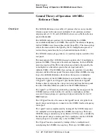
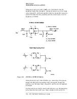
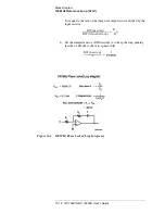
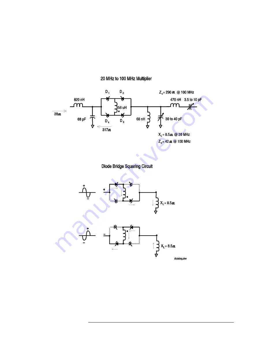
During the positive part of the 20 MHz cycle, current flows from the
impedance transformer, through D1, through the inductor across the bridge
output, through D3, and then through the inductor in the parallel resonator to
ground. The inductor in the parallel resonator has been chosen to be a low
impedance at 20 MHz.
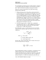
Figure 13-1
20 MHz to 100 MHz Multiplier
During the negative part of the 20 MHz cycle, current flows from ground,
through the inductor in the parallel resonator, through D2, through the
inductor across the bridge output, through D4, and then into the impedance
transformer.
It is important to note that the current in the inductor across the bridge flows
in the same direction in both cases. Since an inductor will not allow its
Summary of Contents for 70427A
Page 11: ...x HP 70427A HP 70428A User s Guide Declaration of Conformity ...
Page 13: ... xii HP 70427A HP 70428A User s Guide Typeface Conventions ...
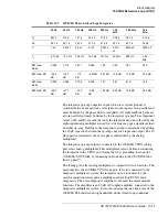
Page 243: ...9 42 HP 70427A HP 70428A User s Guide Technical Data HP 70428A Option 002 Specifications ...
Page 299: ...10 56 HP 70427A HP 70428A User s Guide Softkeys and Displays IF Figure 10 42 μW Mode HP70472A ...
Page 385: ...10 142 HP 70427A HP 70428A User s Guide Softkeys and Displays YTF Cal ...
Page 435: ...12 14 HP 70427A HP 70428A User s Guide Remote Programming Commands ...
Page 607: ...15 10 HP 70427A HP 70428A User s Guide Adjustments 10 MHz Oscillator Adjustment ...
Page 611: ...16 4 HP 70427A HP 70428A User s Guide Customer Support ...


