background image

Summary of Contents for 712B

Page 1: ...HP Archive This vintage Hewlett Packard document was preserved and distributed by www hparchive com Please visit us on the web Scanned by on line curator Tony Gerbic For FREE Distribution Only ...

Page 2: ...OPERATING AND SERVICING MANUAL MODEL 7121 POWER SUPPLY Serial 511 and Above HEWLETT PACKARD COMPANY 275 Page Mill Road Palo Alto California U S A ...

Page 3: ...rd Company The information contained in this booklet is intended for the operation and main tenance of Hewlett Packard equipment and is not to be used otherwise or reproduced without the written consent of the Hewlett Packard Company HEWLEn PACKARD COMPANY 275 PAGE MILL ROAD PALO ALTO CALIFORNIA U S A 7121004 1 ...

Page 4: ...nts 4 3 SECTION II 4 4 Line Regulation Adjustment 4 3 2 1 Controls and Terminals 2 1 4 5 Adjustment of Fixed 300 2 2 Operation 2 2 Volt Bias Supply Output Voltage 4 5 4 6 Adjus tment Of HV Supply SECTION III Output Voltage 4 5 4 7 Setting Variable Resistor 3 1 General 3 1 R39 4 5 3 2 High Voltage Regulator 4 8 Setting the Stop on the H V Circuit 3 1 Control 4 7 3 3 Bias Supply Circuit 3 3 SECTION ...

Page 5: ... microvolts For frequencies above 20 cps Full load 0 1 ohm in series with 25 microhenries maximum No load 1 ohm in series with 50 microhenries maximum Upon application of full load 0 1 millisecond maximum Upon decrease from full load to a 0 ma 0 5 millisecond maximum b 25 ma O 1 millisecond maximum Maximum transient voltage 1 volt o to 200 ma high voltage only Three ranges 0 to 500 volts 0 to 150 ...

Page 6: ... sourcefor small trans mitters oscillators complex systems cer tain types of klystrons and general labora tory use CAUTION The AC power should be turned on for at least 30 seconds before switch ing on the high voltage This allows the regulator circuits to reach their proper operating point and avoids exces sive voltage at the high voltage terminals 1 2 INSPECTION This instrument was thoroughly tes...

Page 7: ...high voltage de cir cuit The fuse may be replaced by turning the fuseholder cap removing the old fuse and inserting a new fuse 2 1 CAUTION If this fuse blows immediately turn off the AC POW ER switch and then replace the fus e Con tinued operation of the instrument with the HV 1 2 AMP fuse open will damage the screen grids of the series regulator tubes V3 V4 V5 V6 HIGH VOLTAGE This toggle switch t...

Page 8: ...re making any connections to the instrument 2 2 The procedure for operating the Model 712B Power Supply is as follows a Connect the power cable to aIlS V power line and turn the AC POWER switch to ON NOTE The triple conductor power cable is supplied with the new NEMA approv ed three prong plug The third con ductor provides a chassis ground An adapter may be obtained to per mit use of this plug wit...

Page 9: ...le re sistor R46 which is connected between the 300V 50 MA terminal and the COM terminal This voltage is regulated against line voltage variations only Since the internal impedance may be as high as 10 000 ohms depending upon the setting of resistor R46 the voltage will depend upon the actual load current be ing drawn 5 rna max This voltage can be measured by turning the METER RANGE switch to the ...

Page 10: ... TRANSFORMER DIFFERENTIAL r o AMPLIFIER POWER INPUT 115V 5O IOOO V VOLTAGE REFERENCE TUBE DIFFERENTIAL AMPLIFIER OUTPUT VOLTAGE 300 VOLT SUPPLY SERIES REGULATOR __ _ 00_ COM 4o 4II O_ 5 MA o BIAS CONTROL lGND 300V 50MA 6 3V AC _ CT IOAMP FILAMENT TRANSFORMER 0 Figure 1 Model 7l2B Block Diagram 3 2 ...

Page 11: ...t 1 000 cycles AC components are cou pled to the grid via resistor R38 and capaci tor C4 DC components pass to the grid through a resistor network R38 R39 R40 R4l 3 3 3 3 BIAS SUPPLY CIRCUIT Arrangement and operation of the regulated bias supply circuit is similar to that of the plate voltage supply circuit except that pri mary current to the bias supply transform er T3 is not variable The bias su...

Page 12: ...3 R6 R36 R45 M2 R38 R39 R40 R34 R35 2 Vl3 R42 1 300V I 50MA Figure 2 Partial Schematic of High Voltage Supply Regulator Circuit 3 4 ...

Page 13: ...itting the brush Any tube in the Model 712B may be replaced with a tube having corresponding RETMA standard characteristics All tubes are accessible when the cover plate or cabinet is removed Location of tubes is shown in Figure 3 Tubes V3 V 4 V5 or V6 may be replaced with a 6L6 6L6 G 6L6 GB or 5881 Replacement of tube VII may make it neces sary to readjust the output voltage of the fix ed 300 vol...

Page 14: ... I tv Figure 3 Model 7l2B Top View Cover Plate Removed ...

Page 15: ...ANSFORMER NOTE The settings of variable resistor R39 and the HV C ONTROL stop ar e set at the factory and should never be touched in the field unless trans former Tl or R39 should require re placement Adjustment procedures to be performed in the event of the replacement of either component are given at the end of this Adjustments paragraph If either Tl or R39 is replaced its respective adjustment ...

Page 16: ... I Figure 4 Mode17l2B Bottom View Bottom Plate Removed ...

Page 17: ...trans former so that 115 volts is applied to the Model 712B d Adjust variable resistor R24 until the test voltmeter reads 300 volts 4 5 4 6 ADJUSTMENT OF HV SUPPLY OUTPUT VOLTAGE a Set up the instrument as in steps a and c of the previous adjustment procedure b With the METER RANGE switch in the 0 500V position and the HV CONTROL in its maximum clockwise position adjust variable resistor R42 see F...

Page 18: ...R38 PIN 2 VI3 R41 R45 PIN 2 VIO TERM D5 T5 RI SRi Figure 5 Model 7l2B Detail of Variable Resistors and Selenium Rectifier 4 6 ...

Page 19: ...ormer wiper ring and remove the stop 4 7 c Attach a DC voltmeter Model 4l0B 1 000 volt range oetween terminal COM on the control panel an4 socket pin 3 of tube V3 d Plug the Model 7l2B power cable into a variable transformer set for 115 volts measured e Turn off the HIGH VOLTAGE switch Set the METER RANGE switch at 0 500V and the HV C ONTR OL to its maximum coun terclockwise position Turn the AC P...

Page 20: ... in trouble measure the DC resistance across the output from each of the three recti fiers Disconnect the instrument from the power line before making the mea surements Normal DC Resistances Across Power Supply Circuits Recti Connect Ohm Approx Normal fier meter Across Resist Ohms VI V2 Socket pin 8 50K VI or V2 and term COM V7 Socket pin 8 2M V7 and term 300V 50 MA SRI Terms of 1 5M capacitor C9 ...

Page 21: ...1y Voltage slightly Fuse F2 HV blown negative Voltage low Fuse F5 300V blown VIO V9 Vl3 V oltage high VII V12 V7 V8 300V Bias Supply Voltage slightly positive V8 V7 Voltage low VII Voltage high V9 VIO Check for open fuse 1 Check for open fuse 2 Check for burned out tube 3 If all tubes are operating check defective tube in suspected circuit by substituting tube known to be good 4 Test external comp...

Page 22: ...T I THRU SAME AS DC CONDITIONS 6 VOLTAGES MEASURED BETWEEN INOICATED POINTS WITH A 1000 OHM I VOLT OR BETTER AC VOLTMETER ALL CAPACITANCE IN wF RESISTANCE IN OHMS UNLESS OTHERWISE NOTED OI lPA S CONT LII M Mi 1 S CR E WQR IVE R A D J I CHASSIS 7r28 R36 390K 00 68 60 R6 1500 OF MODEL ABOVE COPYRIGHT 1954 BY HEWLETT PACKARD This drawlnQ II Intended for he op rotion and malnttl lonee at Hewlett Packa...

Page 23: ...e Table of Replaceable Parts will be listed on a Production Change sheet at the front of this manual When ordering parts from the factory always include the following information Instrument model number Serial number hp stock number of part Description of part ...

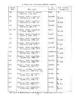
Page 24: ... fixed paper 1 100 0 400 vdcw Capacitor fixed mica 150 100 o 500 vdcw Capacitor fixed paper 0047 200 o 6000 vdcw Resistor fixed wirewound 25 000 ohms 100 o 20 W Resistor fixed composition 1500 ohms 100 o 1 2 W Resistor fixed composition 390 ohms 10 1 W Resistor variable wirewound 100 ohms linear taper Resistor fixed composition 390 ohms 100 o 1 W hp Stock No 17 46 16 56 17 10 16 72 17 12 17 10 16 ...

Page 25: ...500 B 1500 ohms 100 0 1 2 W EB 1521 R19 Resistor fixed compos ition 23 2 2M B 2 2 megohms 100 0 1 2 W EB 2251 R20 Resistor fixed compos ition 24 200K 5 B 200 000 ohms 50 0 1W GB 2045 R21 Resistor fixeq compos ition 24 390K B 390 000 ohms 100 0 1W GB 3941 R22 Resistor fixed compos ition 24 330K B 330 000 ohms 100 0 1W GB 3341 R23 Resistor fixed compos ition 32 179K HP 179 000 ohms 10 0 2W R24 Resis...

Page 26: ...ound 6 ohms 100 0 2 W Resistor fixed composition 1000 ohms 100 0 1 W Resistor variable composition 500 000 ohms 100 0 linear taper Resistor variable composition 50 000 ohms 100 0 linear taper Resistor fixed composition 83 000 ohms 10 0 1 W Resistor variable composition 50 000 ohms 100 0 linear taper Resistor fixed composition 37 000 ohms 10 0 1 W Resistor fixed composition 150 000 ohms 100 0 1 W 2...

Page 27: ...Lampho1der Meter 0 150V 0 500V DC Meter 0 200MA DC Power Cable Reactor 5 H 225 MA Reactor 6 H 125 MA Toggle Switch SPST Toggle Switch DPDT Rotary Switch Assem Rectifier metallic Variable Transformer Power Transformer Power Transformer hp Stock No 23 220 149 4 149 5 M 58 G 83D G 83E M 25 211 46 211 42 211 64 211 67 140 16 712B 74 37 11 211 47 314 3 314 7 145 2 112 26 112 25 812 56 911 49 911 47 310...

Page 28: ...5R4GY zz V3 V4 Tube 6L6GB 6L6 6L6G or 5881 212 6L6GB zz V5 V6 may be used V7 Tube 5Y3GT 212 5Y3GT Zz V8 Tube 6W6GT 212 6w6GT zz V9 Tube 12AX7 212 12AX7 zz VI0 Tube 12AX7 212 12AX7 ZZ VII Tube 5651 212 5651 ZZ V12 Tube 12AX7 212 12AX7 ZZ V13 Tube 12AX7 212 12AX7 ZZ See List of Manufacturers Code Le e6rs For Replaceable Parts Table ...

Page 29: ... Electra Manufacturing Company Acro Manufacturing Company Alliance Manufacturing Company Al cO Electronics Incorporated Astron Corporation el Brothers Incorporated Belden Manufacturing Company Bird Electronics Corporation Barber Colman Company Bud Radio Incorporated Allen D Cardwell Mfg Company Cinema Enginee ring Company Any brand tube meeting RETMA characte r i s tics Corning Glass Works Dale Pr...

Page 30: ......

Reviews: