background image

Summary of Contents for 722A

Page 1: ...HP Archive This vintage Hewlett Packard document was preserved and distributed by www hparchive com Please visit us on the web Scanned by on line curator Tony Gerbic For FREE Distribution Only ...

Page 2: ...HEWLETT PACKARD COMPA Y ...

Page 3: ...01155 1 OPERATING AND SERVICE MANUAL MODEL 722A AR SERIALS PREFIXED 105 DC POWER SUPPLY Copyright HEWLETT PACKARD COMPANY 1961 1501 PAGE Mill ROAD PALO ALTO CALIFORNIA U S A Prioted NOY 1961 ...

Page 4: ... 2 1 2 8 Operation from 230 Volt Supply 2 1 2 11 Preparation for Storage and Shipment 2 1 2 14 Storage 2 1 2 16 Incoming Inspection Perform Test 2 1 III OPERATING INSTRUcrIONS 3 1 3 1 Operation 3 1 3 3 Current Limiting 3 1 3 6 Remote Sensing 3 1 IV PRINCIPLES OF OPERATION 4 1 4 1 Overall Block Diagram 4 1 4 3 Rectifying and Filtering Circuits 4 1 4 6 Series Regulator 4 2 4 8 Output Circuit 4 2 4 1...

Page 5: ... line voltage NOISE AND RIPPLE Less than 250 11 v rms TEMPERATURE STABILITY Better than 0 02 j O C or 5 mvJOC whichever is larger TEMPERATURE RANGE oto 55 0 for operation within specifications OUTPUT IMPEDANCE DC Less than 2 5 milliohms AC Less than 5 milliohms in series with 10 Ilh OUTPUT METERS Voltage 0 to 60 volts one range Current 0 to 2 5 amp one range PROTECTION Output current limiter conti...

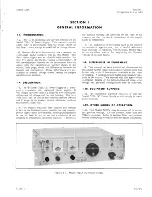
Page 6: ...the load continuously so that you may monitor power supply drain conveniently The output impedance is low for both dc and ac so that a minimum of de coupling is required in cascaded circuits Terminals for remote sensing are provided on the rear of the chassis so that the ohmic resistance of the supply leads is minimized 1 7 The usefulness of the Model 722A is not limited to transistor applications...

Page 7: ...ng to two prong adapter ground third lead green wire externally 2 8 OPERATION FROM 230 VOLT SUPPLY 2 9 This instrument may be used with either a 115 volt or 230 volt supply with a frequency from 50 to 60 cps single phase This instrument is shipped 01155 1 from the factory ready for operation from a 115 volt source unless otherwise indicated Operation from a 230 volt supply is possible by changing ...

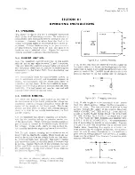
Page 8: ... COARSE and FINE VOLTAGE controls until the voltage on the OUTPUT VOLTAGE meter is of the desired value 3 Adjust CURRENT LIMIT control until the pointer indicates a current value some what greater than the expected value 4 Turn DC POWER switch ON If the OUTPUT VOLTAGE drops when DC POWER is turned on the current limit is probably being exceeded Figure 3 1 Operating Controls 3 0 01155 1 ...

Page 9: ...t Packard as stock number 1901 0019 3 3 CURRENT LIMITING 3 4 The maximum current delivered by this sup ly may be set to any value between 0 1 and 2 amperes This will limit the current to the set value and protect the equipment under test in addition to protecting the transistors in the Model 722A from dissipating too much power 3 5 Occasionally when the current limit control is set to maximum curr...

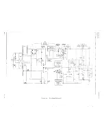
Page 10: ..._ __ J v OV REF R51 R26 R40 10 R25 R33 015 CURRENT LIMITER 04 REFERENCE I I I SUPPLY 0148015 I CURRENT 1 LIMIT fo SKI J C138 TCI4 I 1 I R5A J O I 1 y I I I I I I I R32 10 R3 d 0 200 SIB 0 1 _ CRI6 R31 800 Cf1 IISV 0 3 P _ I I l I AC POWER CRI2 115V 0 o CJ1 CJ1 I Figure 4 1 Simplified Schematic 3 o 0 N N ...

Page 11: ... output voltage The reference power supply furnishes constant volt ages which are used throughout the instrument for reference and supply purposes Terminals are pro vided for remote sensing so the sensing voltage can be connected to the output externally Note In discussions that follow the positive side of the output voltage is considered circllit ground 4 3 RECTIFYING AND FILTERING CIRCUITS 4 4 R...

Page 12: ...gnal is amplified and inverted in Q11 and fed to the base of Q2 This signal tends to increase the current through Q2 another pnp type transistor Increasing the current through Q2 increases the volt age out of the supply Since the original action was a decrease in voltage this action will tend to restore the original conditions regulating the supply 4 13 The dc output voltage is set by varying the ...

Page 13: ... is first turned on the relay Kl is in the opposite position to that shown in the schematic at the end of this manual The voltage applied 01155 1 to the coil of Kl must first charge capaCitors C13 and C14 through R31 before the relay coil becomes energized When these capacitors charge up the relay coil will become energized and the relay contacts will switch providing a time delay in turn on The t...

Page 14: ...former olution and 1 accuracy Low Heat 23 1 2 watt element Solder printed circuit boards Soldering Iron connect iron to 75 volt line Ungar Model 776 Soldering Iron Handle Ungar Model 535 Heater Element Ungar Model PL333 Soldering Iron Tip Stable Voltage oise and ripple less than Reference voltage to test Another Model 722A Source 250 microvolt at 60 volts regulation 45 volt and 7 volt battery conn...

Page 15: ...it board missing 5 9 The printed circuit boards are held in by being plugged into sockets Since these sockets have many 01155 1 contacts the board is held in quite firmly without being fastened in any other way To remove these boards some additional help may be needed Place a screw driver right angle screwdriver with boards A B under the end of the board nearest the chassis and pry up 5 10 TEST EQ...

Page 16: ...Section V Figure 5 1 REMOTE LOCAL SWITCH S 3 TERMINAL STRIP FOR 230V CONVERSION IF UNIT DOESN T HAVE 115V 230V SWITCH Model 722A MP S 894 5 2 Figure 5 1 Model 722A Bottom View 01155 1 ...

Page 17: ...Model 722A Section V Figure 5 2 1 1155 1 MP S 895 Figure 5 2 Model 722A Top View 5 3 ...

Page 18: ...nsive damage to the etched circuit board will result 1 Apply heat sparingly to lead of component to be replaced If lead of component passes through an eyelet in the circuit board apply heat on com ponent side of board If lead of component does not pass through an eyelet apply heat to CQii ductor side of board 3 Bend clean tinned leads on new part and care fully insert through eyelets or holes in b...

Page 19: ...Check CRl CR2 CR3 CR4 CRI2 CRI3 CRI4 CRIS CRI6 CR22 CR23 shorted winding on T 1 or brush and winding on T2 CR7 CR8 CR9 CRI0 Voltage CR7 should be about 0 8 volts Current limiting recalibrate cur rent limits Current limiting Output C6 Poor load regulation CR5 CR11 CRI7 Q2 Q4 Q11 Q12 Q13 R33 and S3 CRII Load regulation and transients with dc switching 1 Loosen fan by removing four allen head screws ...

Page 20: ...minal on the Model 722A is considered ground 5 6 Model 722A 5 29 CURRENT LIMIT 5 30 A simple way to measure current with a volt meter is to use a load made up of a 25 ohm 150 watt resistor in series with a precision 1 1 ohm S watt resistor r 5f stock number 0811 0040 Connect a volt meter in shunt with this precision resistor In the following procedure the term shunt voltmeter will be used to disti...

Page 21: ...5 1 Section V Paragraphs 5 36 to 5 40 5 39 RIPPLE CHARACTERISTICS Note The instrument under test must not be lying on magnetic material for this test a Connect a voltmeter and load as instructed in paragraph 5 36 Current Limiting This voltmeter will be called the shunt voltmeter b Connect an oscilloscope as instructed in para graph 5 38 Operation Characteristics c Connect a floating battery operat...

Page 22: ...lts and note the output voltage change This change should be 2 5 millivolts or less r SCHEMATIC DIAGRAM NOTES 1 Heavy solid line shows main signal path heavy dashed line shows control secondary signal or feedback path 2 Heavy box indicates front panel engraving light box indicates chassis marking 3 Arrows on potentiometers indicate clockwise rotation as viewed from the round shaft end counterclock...

Page 23: ...45 AI2 52 6K ci3 CR24 AI 100V REFERENCE CR25 I J CR26 VOLTAGE C21 C22 ADJUST 27V R50 20 100 1000 UF UF 8 COPYRIGHT 1961 BY HEWLETT PACKARD COMPANY This drawing is Intended for the operation and maintenance of Hewlett Packard equip ment and Is not to be used atherwise or reproduced without written consent of the Hewlett Packard Company 722 A tt PI T 100 Figure 5 4 Reference Power Supply 01155 1 5 9...

Page 24: ... _ U 230V rACl FI 115V 230V SWITCH OPTION PI PI rAn Lf SIA OR SLOW BLOW 2 5 AMP COPYRIGHT 1961 BY HEWLETT PACKARD COMPANY Thl drawln I Intended for the operation and maintenance of Hewlett Packard equip ment and I not to be u ed otherwi e or reproduced without written con ent of the Hewlett Packard Company 722 PS I 0 ZI TlOS Ie Figure 5 5 Power Supply sheet 1 of 2 5 10 01155 1 ...

Page 25: ...4 R4 B R8 O II 1000 1000 B4 7 _ _ _ 1 I f Iv __ 4 JV v I O CI J R5A B8t L R I O R 5B B4t t It t I BIO rJ t t t J 8 5000 3 C4 R24 A17 AI RI4 CW 00 CW R20 I UF 100 CW r R9 100 CW 2000 CW R29 47K RII IA 2 2A I FINE d 100 BII R6 600 LIMIT ADJ B12 LIMIT ADJ v C5 W w II 1 L 5 J 61 10 0 _ C 1t 7 I f C3 20UF VOLTAGE B il 35UF U 4 B5 R25 I II 1 I CW 5000 L 1 1 _ _ 1 ICURRENT LIMIT A7 f OV REF R51 1000 AI4 ...

Page 26: ...S assembly motor capacitor diode delay line device signaling lamp F FL J K L M fuse filter jack relay inductor meter REFERENCE DESIGNATORS P plug Q transistor R resistor RT thermistor S switch T transformer v vacuum tube neon bulb photocell etc W cable X socket XF fuseholder XV tube socket XDS lampholder ABBREVIATIONS elect electrolytic mtg mounting encap encapsulated my mylar obd order by de scri...

Page 27: ...ption fxd elect 3500 uf 100 vdcw fxd my 0 047 uf 10 200 vdcw fxd elect 35 uf 100 10 6 vdcw fxd my 0 1 uf 20 100 vdcw fxd elect 20 uf 150 vdcw fxd elect 500 uf 75 vdcw Not Assigned fxd elect 100 uf 100 vdcw Same as C5 fxd elect 100 uf 25 vdcw fxd my 0 01 uf 5 400 vdcw Not Assigned Same as C5 Same as C11 fxd elect 20 uf 25 vdcw Diode si 1N1344 Diode si 500 rna 400 PIV Diode si Same as CR1 Diode si D...

Page 28: ...0263 var ww dual ganged front sect 5K ohms 10 2 W rear sect lin 300 ohms 10 2 W R6 0693 5621 fxd comp 5600 ohms 10 2 W R7 0813 0026 fxd ww 800 ohms 10 5 W R8 Same as R4 R9 0687 4731 fxd comp 47K ohms 10 1 2 W RIO 11 0813 0025 fxd ww 600 ohms 10 5 W R12 0690 8221 fxd comp 8200 ohms 10 1 W R13 0687 4701 fxd comp 47 ohms 10 1 2 W R14 2100 0118 var comp 100 ohms 20 0 2 W R15 0727 0110 fxd dep c 1500 o...

Page 29: ... 2 W Same as R7 fxd comp 10 ohms 1O 1 W Consists of approximately 11 inches of stranded 22 wire adjusted at factory fxd comp 220 ohms 10 1 2 W fxd comp 3600 ohms 5 1 2 W fxd comp 560 ohms 10 1 2 W fxd comp 270 ohms 10 1 2 W fxd comp 12000 ohms 10 1 2 W Same as R17 fxd comp 10 ohms 1O 1 2 W fxd ww 350 ohms 10 5 W fxd ww 450 ohms 10 5 W fxd comp 10K ohms 10 1 2 W fxd dep c 52 600 ohms 1 1 2 W fxd co...

Page 30: ...nding post 3 hole black output Binding post red output terminal Coupler bellows 1 4 to 3 8 shaft Knob black 23 4 COARSE VOLTAGE Knob black 3 4 w pointer CURRENT LIMIT FINE VOLTAGE Guide printed circuit Clamp stop coarse voltage Assembly circuit board A Assembly circuit board B Assembly circuit board C Holder air filter Insulator transistor mounting Socket transistor mounting Connector printed circ...

Page 31: ...6289 D32611 2 1 0180 0096 fxd elect 3500 uf 100 vdcw 56289 type 32D 1 1 0360 0079 Board terminal 5 terminal 71286 Order by description 1 0 0490 0032 Relay inductor 2500 ohms 10 71482 R A 110526 1 1 0686 3625 fxd comp 3600 ohms 5 1 2 W 01121 EB 3625 1 1 0687 1001 fxci comp 10 ohms 10 1 2 W 01121 EB 1001 1 1 0687 1011 fxd comp 100 ohms 10 1 2 W 01121 EB 1011 2 1 0687 1031 fxd comp 10 000 ohms 10 1 2...

Page 32: ... 1 1 description 0813 0023 fxd ww 350 ohms 10 5W 35434 CN5 order by 2 1 description 0813 0024 fxd ww 450 ohms 10 5W 35434 CN5 order by 1 1 description 0813 0025 fxd ww 600 ohms 10 5W 35434 CN5 order by 2 1 description 0813 0026 fxd ww 800 ohms 10 5W 35434 CN5 order by 2 1 description 0813 0027 fxd ww 1K ohms 10 5W 35434 CN5 order by 2 1 description 1120 0103 Meter 0 60 volts 06555 type 2PL order b...

Page 33: ...V operation Fuse cartridge 1 25 amp slow blow for 230 V operation Switch slide DPDT Switch toggle DPDT SWitch toggle 3PDT Switch slide DPDT Cord power Transformer power Transformer variable 115 V input 0 115 V output 0 135 V output Inductor fixed 5 0 mh Mfr 01295 11237 11237 11237 11237 11237 24655 11237 71400 71400 42190 04009 88140 42190 70903 98734 24655 99848 Mfr Part No IN2069 type 252 order ...

Page 34: ...uide printed circuit Clamp stop coarse voltage Assembly circuit board A Assembly circuit board B Assembly circuit board C Holder air filter Insulator transistor mounting Socket transistor mounting Connector printed circuit 15 pin Connector printed circuit 18 pin Filter air Fan 100 CFU 115 VAC 10 50 60 cycles 14W 28480 28480 28480 28480 28480 28480 28480 28480 28480 28480 28480 28480 76530 83298 95...

Page 35: ... Chicago Telephone of California Inc So Pasadena Calif Microwave Electronics Corp Palo Alto Calif Palo Alto Calif Dover N H General Electric Co G E Lamp Division Nela Park Cleveland Ohio General Radio Co West Concord Mass Grobet File Co of America Inc Carlstadt N J Hamilton Watch Co Lancaster Pa Hewlett Packard Co Palo Alto Calif G E Receiving Tube Dept Owensboro Ky Lectrohm Inc Chicago III P R Ma...

Page 36: ...gat Brothers lnc Attleboro Mass Dale Products Inc Columbus Neb Eleo Corp Philadelphia Pa Gremar Mfg Co Inc Wakefield Mass K F Development Co Redwood City Calif Micro Switcn Div of Minneapolis Honeywell Regulator Co Freeport III Universal Metal Products Inc Bassett Puente Calif Sylvania Electric Prod Inc Semiconductor Div Woburn Mass Robbins and Myers Inc New York N Y Stevens Mfg Co Inc Mansfield O...

Page 37: ...ke changes shown in tables Instrument Serial Prefix Make Manual Changes Instrument Serial Prefix Make Manual Changes 105 1 2 CHANGE 1 Figure 4 3 Change reference designator R13 to R14 Figure 5 4 5 5 Change reference supply voltage to 13 8 0 2 volts Paragraph 5 23 step b Change to read 13 8 0 2 volts until the meter reads CHANGE 2 4 12 62 Figure 5 5 Change Amplifier Q12 from 2N247 to 2N274 ...

Page 38: ...P R I N TED I N U S A ...

Reviews: