background image

Artisan Technology Group - Quality Instrumentation ... Guaranteed | (888) 88-SOURCE | www.artisantg.com

Summary of Contents for 75000 SERIES C

Page 1: ...l service in house repair center WE BUY USED EQUIPMENT Sell your excess underutilized and idle used equipment We also offer credit for buy backs and trade ins www artisantg com WeBuyEquipment REMOTE INSPECTION Remotely inspect equipment before purchasing with our interactive website at www instraview com LOOKING FOR MORE INFORMATION Visit us on the web at www artisantg com for more information on ...

Page 2: ...S This manual applies to all instruments F aHEWLETT PACKARD HP Part No E1440 90011 MicrofichePart Number E1440 95011 Printed i n the Federal Republic of Germany April 1992 Second Edition E0492 Artisan Technology Group Quality Instrumentation Guaranteed 888 88 SOURCE www artisantg com ...

Page 3: ...ment that is not furnished by HP Use duplication or disclosure by the Government is subject to restrictions as set forth in subdivision b 3 ii of the Rights in Technical Data and Computer Software clause at 52 227 7013 Hewlett Packard Company 3000 Hanover Street Palo Alto California 94304 The instrument photograph on the front cover shows the HP E1440A This document contains proprietary informatio...

Page 4: ...uct has been designed and tested according to International Safety Requirements To ensure safe operation and to keep the product safe heed the symbols warnings and cautions contained in this section Operational Safety The following general safety precautions must be observed during all phases of operation service and repair of this product Failure to comply with these precautions or with specific ...

Page 5: ...aintained Safety Symbols A The apparatus will be marked with this symbol when it is necessary for the user to refer to the instruction manual in order to protect the apparatus against damage Indicates dangerous voltages I Earth terminal I Protective earth A Affixed to a product containing static sensitive devices use anti static handling procedures ATTENTION to prevent electrostatic discharge dama...

Page 6: ...ll be uninterrupted or error free Limitation of Warranty The foregoing warranty shall not apply to defects resulting from improper or inadequate maintenance by Buyer Buyer supplied products or interfacing unauthorized modification or misuse operation outside of the environmental specifications for the product or improper site preparation or maintenance The design and implementation of any circuit ...

Page 7: ...eclaration This is to certify that the equipment HP E1440A meets the radio frequency interference requirements of Directive FTZ 1046184 when used in the HP 75000 Series C System The German Bundespost has been notified that this equipment was put into circulation and has been granted the right to check the product type for compliance with these requirements Additional Information for Test and Measu...

Page 8: ...rmation Setting up and sample programs programming techniques Chapters 3 and 4 Programming Information Explanation of each software command applicable to the HP E1440A Chapter 5 Appendix B and Appendix D Specifications Appendix A Customer Assistance Sales and Service information Appendix F vii Artisan Technology Group Quality Instrumentation Guaranteed 888 88 SOURCE www artisantg com ...

Page 9: ... TTL X Drive Pen lift Sync Out TTL Output Ref Out lOMHz Ref In 1 1OMHz AM f 5V PM f 5V Front Panel Indicators Failed Access Error Output On Caution 2 Coniiguring the HP E1440A Using this Chapter Inspection Claims and Repackaging Storage and Shipment Return Shipments to HP Configuration The Logical Address Switch Changing Module Settings Installation Installing the HP E1440A Artisan Technology Grou...

Page 10: ...Chapter A System Overview The VXIbus Interface The Microprocessor System The Synthesizer The Function Generator The Output Unit Amplifier Attenuator Sweep Generator Front Panel Planning and Programming The HP E1440Ain a Test Environment Signal Parameters FREQuency AMPLitude OFFSet PHASe Value Coupling General Example Example of processing value coupled commands Sweep Example Functional Coupling SO...

Page 11: ...5 Parameters 5 6 Linking Commands 5 7 Common Command Format 5 7 SCPI Command Reference 5 8 ABORt 5 8 Subsystem Syntax 5 8 Comments 5 8 Example 5 8 CALibration 5 9 Subsystem Syntax 5 9 Comments 5 9 CAL Results 5 9 INITiate 5 11 Subsystem Syntax 5 11 CONTinuous 5 11 Parameters 5 11 Comments 5 11 IMMediate 5 11 Comments 5 11 OUTPut 5 12 Subsystem Syntax 5 12 STATe 5 12 Parameters 5 12 Comments 5 12 S...

Page 12: ... LIST Subsystem Syntax LIST FREQuency LIST DWELl LIST SEQuence SOURce MARKer n Subsystem Syntax Comments SOURce PHASe Subsystem Syntax Comments Example SOURce PM Subsystem Syntax Parameters Comments SOURce ROSCillator Subsystem Syntax Comments SOURce SWEep Subsystem Syntax SWEep TIME SWEep TIME RETRace Comments STATUS STATus OPERation Subsystem Syntax comments STATus QUEStionable STATus QUEStionab...

Page 13: ...0fl Sinewave Spectral Purity Squarewave Characteristics Typical Triangle Ramp Characteristics DC Offset Phase Offset Sinewave Amplitude Modulation Typical Phase Modulation Typical Frequency Sweep Auxiliary Outputs Typical Auxilliary Inputs Typical VXIbus Interface Capabilities Option 001 High Voltage Output Amplifier General Typical refer to VXI System Specification Artisan Technology Group Qualit...

Page 14: ...ts Introduction Harmonic Distortion Specifications Equipment Required Procedure High Voltage Output Option 001 Spurious Signal Specifications Equipment Required Mixer Spurious Procedure Close in Spurious Fractional N Spurs Procedure Integrated Phase Noise Specifications Equipment Required Procedure Frequency Accuracy Specifications Equipment Required Procedure Phase Increment Accuracy Specificatio...

Page 15: ...ipment Required Procedure Test Facility Test Conditions Installed Options Ambient Temperature Relative Humidity Line Frequency Special Notes Test Equipment Used Harmonic Distortion Spurious Signals Integrated Phase Noise Frequency Accuracy Phase Increment Accuracy Amplitude Accuracy DC Offset Accuracy DC only DC Offset Accuracy with AC Function Triangle Linearity D Command Quick Reference Introduc...

Page 16: ...1 South East Europe F 1 Middle East and Central Africa F 2 United Kingdom F 2 United States of America F 2 Eastern USA F 2 Midwestern USA F 2 Southern USA F 2 Western USA F 2 Other International Areas F 3 Index Artisan Technology Group Quality Instrumentation Guaranteed 888 88 SOURCE www artisantg com ...

Page 17: ...cation Test Set Up High Voltage Output C 12 C 4 Mixer Spurious Test Set Up C 14 C 5 Integrated Phase Noise Test Set Up C 17 C 6 Phase Increment Accuracy Test Set Up C 20 C 7 Function Amplitude Accuracy Test Set Up C 23 C 8 High voltage sinewave accuracy test set up C 26 C 9 Function Amplitude Accuracy Test Set Up High Voltage Output C 27 C 10 Test set up for Amplitude Accuracy Adjustment Frequency...

Page 18: ...ommand Group Assignment 4 6 Illegal El440 Commands in FREQ MODE LIST SWEEP 5 1 Operation Status Register 5 2 Questionable Status Register 5 3 Questionable Frequency Register 5 4 Common Command Summary 5 5 Reset State Standard Setting C 1 Recommended Test Equipment for Tests C 2 Self test result bits C 3 Service Switch Parameter Settings C 4 Artisan Technology Group Quality Instrumentation Guarante...

Page 19: ...hase a function generator Produces various waveforms at a specified frequency amplitude DC offset and phase a sweep generator Produces logarithmic and linear frequency sweeps Key Features Key features of the HP E1440A are as follows 5 different waveforms can be output Variable offsets and amplitudes rn Can be used as a DC source rn Multi interval or multi marker sweep capabilities rn Sweep sequenc...

Page 20: ...Artisan Technology Group Quality Instrumentation Guaranteed 888 88 SOURCE www artisantg com ...

Page 21: ...s If you are not familiar with these then refer to industry standard publications about the VMEbus and the following publications rn The VXIbus System Specification7 published by The VXIbus Consortium Inc rn ANSIIIEEE 488 2 1987 Digital Interface for Programmable Instrumentation published by the Institute of Electrical and Electronic Engineers A complete syntax list of the HP E1440A programming co...

Page 22: ...e is at a primary interface address of 09 and the synthesizer is at a secondary address of 11 The program also assumes that an HP 9000 Series 200 300 computer is used Send t h e s e l f t e s t command t o t h e synthesizer I OUTPUT 70911 ll TST l I Enter and display the s e l f t e s t code I ENTER70911 A PRINT A Reset t h e synthesizer I OUTPUT 70911 RSTI1 END Note 3 Last line of program After t...

Page 23: ...rker n Marker Frequency n Sweep Time Automatic Sweep Trace Sweep Direction Reference Oscillator Source Reference Oscillator Automatic Function AM State PM State Output Output Amplifier HV Opt 001 TTL Trigger Output n TTL Trigger Output Source n Phase Phase Step Phase Units SAV n Reset State IFF mV P P 1 V dolts 1Hz FIXed 3 Hz 2 1 MHz 3FF SENTer 3FF n is 1to 9 I Hz n is 1to 9 I s 3N UP SINe OFF OFF...

Page 24: ...otiHz Ref In 11lOMHr 6 Float i Figure 1 2 HP E1440A Front panel Marker TTL This TTL compatible output goes low at the selected marker frequency during a sweep and goes high at completion of the sweep in the multi interval mode In the multi marker mode the signal pulses low at the selected marker frequency 1 6 Getting Started Artisan Technology Group Quality Instrumentation Guaranteed 888 88 SOURCE...

Page 25: ...hase lock the internal 30 MHz oscillator AM f 5V An Amplitude Modulation input reference can be connected here for input to the synthesizer circuit Range is 5 volts in all modes i e sine square triangle ramps PM f 5V A Phase Modulation input reference can be connected here for input to the synthesizer circuit Range is f5 volts in all modes i e sine square triangle ramps Front Panel Indicators Fail...

Page 26: ...is green lamp illuminates when there is a signal available at the output connector Caution The outputs and externally applied voltages may be floating at upto 42 V Risk of electric shock may exist The input output connectors should not be subjected to overload Carefully note the max applicable voltage for each connector as specified in Appendix A to this manual 1 8 Getting Started Artisan Technolo...

Page 27: ...damaged it should be kept until the contents of the shipment have been checked for completeness and the instrument has been verified both mechanically and electrically Procedures for checking the operation of the instrument are given in Chapter 1 Getting Started If the contents are incomplete mechanical damage or defect is apparent or if an instrument does not pass the operator s checks notify the...

Page 28: ...ble or reusable General instructions for repacking are as follows 1 Wrap instrument in heavy paper or plastic 2 Use strong shipping container A double wall carton is adequate 3 Use enough shock absorbing material 3 to 4 inch layer around all sides of the instrument to provide a firm cushion and prevent I movement inside container 4 Seal shipping container securely 5 Mark shipping container FRAGILE...

Page 29: ...setting of 88 which is equivalent to a secondary address of 11 Figure 2 2 shows how a primary address setting of 88 transposes to a secondary address of 11by shifting three places ignoring the first three switches Make sure you apply this rule when altering the switch setting to a number of your choice Remember the module secondary address must be the one present in a l l control programs for this...

Page 30: ...ere are several connecting links which you can change to alter the module configuration for control interrupt priority The link locations are shown on Figures 2 1 2 2 and configurations are shown on Figure 2 3 Access is gained through a cutout in the cover Jumpers JlOl to J106 can be used to alter the interrupt priority setting of the HP E1440A module In most cases this would not need to be altere...

Page 31: ...iBRO BGIBR1 BGiBR2 BGiBR3 Factory setting Figure 2 3 Jumper 5101 Links Settings A The Jumper positions are factory set as shown Do L A not alter unless absolutely necessary lnstallation In addition to C Size modules the mainframe also accepts A and B Size modules If you intend using the HP E1440A with these smaller size modules it is better to install them first Refer to the mainframe manual for d...

Page 32: ... connector receptacles which could be damaged or altered if the module connectors are pushed against them Carefully push the module home so that the connectors mate solidly with the back plane receptacles the screening fingers rest comfortably against the adjacent module and the front panel is flush against the front bar of the mainframe rn Secure the module using the captive screws in the front p...

Page 33: ...within the unit has checked that it is connected properly to the VXIbus and can operate with the rest of the system To check if the controller and the HP E1440A are talking with each other send a query and look at the response from the HP E1440A For example Program Result 10 DIM A 2551 Dimensions A 20 OUTPUT 70911 Queries the type of output waveform the FUNC HP E1440A is set to 30 ENTER 70911 A Th...

Page 34: ... switches the output signal The HP E1440A may use alternative reference oscillators as follows Source Keyword Description ROSC SOUR An internal 30 MHz crystal INTernal ROSC SOUR A reference input to the front panel connector in EXTernal the range 1MHz to 10 MHz ROSC SOUR A 10 MHz signal taken from the VXIbus CLK 10 available to a l l mainframe modules The function FUNC SHAPe command allows you to ...

Page 35: ...lti marker sweep generator A l l of the programs assume the following rn an HP 9000 Series 200 or 300 Computer as controller rn that BASIC is the programming language rn that the HP E1440A is preset to HP IB address 11 rn that the slot 0 commander E1405 is set to primary HP IB address 9 Function Generator The following program shows an example of how to program the HP E1440A as a function generato...

Page 36: ...am assumes that the amplitude waveform DC offset and phase are the same as set in the previous example retrace time is set to 5 seconds and the sweep is t o run continuously The program then shows how to set five sweep intervals with the following parameters Interval 1 start frequency 1kHz stop frequency 3 kHz marker frequency 2 kHz sweep time 1sec sweep mode linear Interval 2 start frequency 500 ...

Page 37: ...t Frequency 1 0 kHz Interval Stop Frequency 5 0 kHz Interval Sweep Time 1 0 s with the following markers Marker 1 1 5 kHz Marker 2 2 0 kHz Marker 3 2 5 kHz Marker 4 3 0 kHz Marker 5 3 5 kHz Marker 6 4 0 kHz Marker 7 4 5 kHz 1 OUTPUT 70911 It FREQ STAR 1E3 2 OUTPUT 70911 It FREQ STOP 5E3 3 OUTPUT 70911 MARKl FREQ l SE3 MARK2 FREQ 2E3 4 OUTPUT 70911 MARK3 FREQ 2 5E3 MARK4 FREQ 3E3 5 OUTPUT 7091l MAR...

Page 38: ...ecause an offset of 0 1 V is incompatible with an amplitude of 2 V leftover from second measurement Reverting the order of programming first offset then amplitude will just move the problem not eliminate it In this case you will get an error at the first VOLT OFFS command because an offset of 0 1 V is incompatible with an amplitude of 0 001 value after RST There are three ways out of the dilemma 1...

Page 39: ...40 VOLT AMPL 0 1 V OFFSET 0 2 V D o measurement 3 END Using OPC to This example program demonstrates the use of the OPC to Synchronize the HP synchronize the controller with the E1440 It also shows how one 1 4 4 0 can deal with the LIST subsystem which can sometimes be slightly unwieldy The requirement is to set up a list sweep comprising rn one lin interval 1MHz to 13 MHz 1 second one equi interv...

Page 40: ...E A L Lstop 1 10 stop frequencies 180 R E A L Ltime 1 10 dwell times 190 DIM Lspac 1 10 C51 spacing modes 200 DIM Lseq 801 sequence 210 DIM Opc resp C31 f o r entering t h e OPC response 220 230 INTEGER I t h e famous a l l purpose I 240 INTEGER No of int number of i n t e r v a l s 250 260 R E A L El440 f o r t h e instruments HP IB address 270 Notice t h a t an INTEGER is too small t o hold 280 ...

Page 41: ... last param NEXT I OUTPUT El440 I output CR LF at end of list I now we do the same as above for stop spacing and dwell list I OUTPUT El440 I LIST FREQ STOP FOR I 1 TO No of int OUTPUT E1440 Lstop I IF I No of int THEN OUTPUT El44O I1 NEXT I OUTPUT El440 I OUTPUT El440 LIST FREQ SPAC FOR I 1 TO No of int OUTPUT El44O Lspac I IF I No of int THEN OUTPUT E1440 1f tl NEXT I OUTPUT El440 OUTPUT El440 LI...

Page 42: ...se w i l l not be sent by the El440 u n t i l the currently 1010 running sweep stops 1020 note t h a t t h i s may cause an I O timeout on the controller i f 1030 timeout is s e t too short f o r the HP IB interface 1040 1050 OUTPUT El440 OPC 1060 ENTER E1440 0pc resp 1070 1080 ready p r i n t the message and end 1090 1100 PRINT L i s t sweep finished 1110 1120 END 3 10 Using the HP E1440A Artisan...

Page 43: ... a t an INTEGER is too small t o hold a HP IB address with secondary addressing E1440 70911 assumed s l o t 0 commander is connected t o HP IB interface with s e l e c t code 7 primary HP IB address of s l o t 0 commander is 9 and logical address of El440 is 11 secondary HP IB address is logical add s h i f t e d l e f t 3 b i t s To start with we put instrument i n t o a known s t a t e CLEAR El4...

Page 44: ...OUTPUT E1440 WAI VOLT 9 INITu Wait f o r completion of l a s t sweep cycle and switch output off OUTPUT E1440 WAI OUTP OFF END 3 12 Using the HP E1440A Artisan Technology Group Quality Instrumentation Guaranteed 888 88 SOURCE www artisantg com ...

Page 45: ... 1 Planning and Programming 4 4 The HP E1440A in a Test Environment 4 5 Value Coupling 4 9 Functional Coupling 4 13 Programming Pitfds 4 14 A System Overview The E1440A Synthesizer consists of five main sub units as follows 1 VXIbus Interface 2 Microprocessor System 3 Synthesizer 4 Function Generator 5 Output Unit These units are illustrated in Figure 4 1 below M b u s H Microcomputer and Interfac...

Page 46: ... noise and possible voltage variations This part of the HP E1440A includes the microprocessor associated ROM and RAM areas decoders and peripheral devices It maintains overall control of the whole unit Wbvs Interface Conhoi Sample 8 Hold 30 to 6OMHz 30 to 60MHz sync Out l 7 L 0 6 0 M M If vcol If re6 0 to 21MHz mto samde boa Func Generator Figure 4 2 Synthesizer Block Diagram The synthesizer produ...

Page 47: ...pedance and applies a multiplication factor if required Sweep Generator This circuit generates control signals required by external equipment such as plotters and chart recorders that require synchronization and markers for subsequent analysis of traces A normal test requirement would be for test frequencies generated by the HP E1440A to be applied to the unit under test UUT and it s output record...

Page 48: ...w charted Note llrC With conventional test equipment the approach is less disciplined because in most cases a user can pause in the task manually reset and select alternative control settings as required by the test procedure he is following and then continue Description of available programming commands and their syntax notation are provided in Chapter 5 Command Reference Some sample programs are...

Page 49: ... 4 1 Frequency Ranges I Function I Ranee I SINE WAVE SQUARE WAVE TRIangle 1 pHz to 21 MHz 1pHz to 11MHz 1pHz to 11 kHz High Voltage Option Output Amplifier OUTPut AMPLify When the high voltage output is used option 001 is installed the load resistance must be greater than 500 I 2 or distortion will result particularly at higher frequencies The maximum frequency for the sine and square waveforms is...

Page 50: ... 5 of the peak to peak output the total capacitance connected to the output should be 500 pF An error will occur if the amplitude is given in dBm for the high voltage option The amplitude limits for the high voltage option are shown in Table 4 3 The ranges given are only applicable when no DC offset has been specified When this is the case see Table 4 4 Note When the high voltage option is switche...

Page 51: ...l illuminate on the front panel and the entry value is not accepted Offset Only No AC Function When the DC function is activated then no AC function is activated The DC voltage output may then be programmed from 0 mV to f5 V with 4 digit resolution AC with DC Offset When DC offset is added to any AC function there are minimum and maximum offset limits which must be observed These limits are affect...

Page 52: ... Voltage Option Factor When the high voltage output is used option 001 is installed the minimum and maximum permissible DC offset voltages may be determined by multiplying the amplitude and offset values in Table 4 4 by four The equation given on the previous page must be changed to Maximum DC offset 2 0 1 Amptdl2 where A Attenuation factor from Table 4 4 and Amptd Amplitude in V p p of the AC fun...

Page 53: ... HP E1440A will then cause the phase between the two instruments to change accordingly Note In this case the phase relationships of the two instruments are not calibrated just locked For square wave frequencies below 25 kHz phase changes greater than 25 may result in a phase shift of f180 from the desired amount The phase limit is f720 0 with a resolution of 0 1 After entering a phase shift the ne...

Page 54: ...Table 4 5 El440 Command Group Assignment Command 4 10 Understanding the HP E1440A Artisan Technology Group Quality Instrumentation Guaranteed 888 88 SOURCE www artisantg com ...

Page 55: ...and for an example The following pseudo variables and functions are used in the description Variable Description LAST GROUP is the group id of the most recent received command it is set to 0 after power on THIS GROUP is the group id of the current command CLEAN UP is a routine that executes pending commands STORE is a routine that stores pending commands EXEC is a routine that executes the current...

Page 56: ...composed of commands with the following group assignments s u f i AO B1 C1 DO E2 F2 G3 H3 CR LF Such a program message would be processed in the following manner A THIS GROUP O LAST GROUP assumed O A is executed B THIS GROUP 0 LAST GROUP 0 B is made pending C THIS GROUP LAST GROUP 0 C is made pending D THIS GROUP 0 LAST GROUP B and C are executed D is executed E THIS GROUP 0 LAST GROUP 0 E is made...

Page 57: ...ng to re program dozens of parameters if he does not want to sweep this function Example Assume a user has set up 50 intervals all sweeping in the range of 10 to 21 MHz and he wants to switch the waveform to triangle temporarily In a strict approach this is not allowed unless he reprograms dl 50 intervals because the maximum frequency for output function triangle is 11kHz b Functional Coupling SOU...

Page 58: ...eir query is allowed has a special effect when issued while the instrument is in FREQ MODE SWEEP or in FREQ MODE LIST The commands are given in their short form with optional command nodes deleted trailing ellipses on a command indicate that the table entry is valid for all sub commands that might follow the command Command aliases e g VOLT I POW I CURR are not shown Table 4 6 Illegal El440 Comman...

Page 59: ...g 1 INIT is legal IN MODE sweepjlist ONLY An error is generated if it is received while in mode CW I FIX or while a sweep is already running 2 If a frequency is entered while in mode sweepllist then the frequency mod is switched to CW NAP Not Applicable that means that either the query only or the non query form of a command exists ILL ILLegal the commandjquery is not allowed In the case of a quer...

Page 60: ... into an illegal marker by touching nothing except the sweep dwell time Example 2 identical but sweep time is significantly shorter I FREQ START 1kHz FREQ STOP 3 kHz SWE TIME 0 1 FUNC TTL and FUNC For the output FUNCtions TTL and DC some instrument DC limitations parameters are fixed The commands affected for FUNCtion TTL are VOLT and VOLT OFFS the commands affected for FUNCtion DC are FREQ and VO...

Page 61: ...ll query responses are given in the default unit The effective unit is used when the volt value is checked against bounds observe that the transformation rules from dBm or VRM to V are different for different output functions The hardware limits are V limits rn an attempt is made to switch the output amplifier on this is not possible when the real unit is dBm the dBm value is only correct for a 50...

Page 62: ...IT CONT ON WAI more commands more commands might be whatever You want it does not matter because it will never be seen by the parser issue a Device Clear or Selected Device Clear command to the instrument Using HP Rocky Mountain BASIC this can be done as follows 1000 El440 is at VXIbus address 70911 1010 Select code of controllers VXIbus interface card 7 1020 Primary VXIbus address of Slot 0 comma...

Page 63: ...nds perform functions for making measurements and setting output levels or data retrieval A command subsystem structure is hierarchical usually consisting of a top root level command with one or more low level commands and their parameters The following example shows a typical subsystem SOURce is the root command VOLTage POWer are secondary level commands and LEVel UNIT are third level commands Th...

Page 64: ...message consists of one or more program message units see below separated by program message unit separators semicolon and terminated by a program message terminator carriage return line feed abbreviated as CR LF sequence An example for a program message is VOLT OFFS 1V FREQ 5 kHz CR LF Note As you see the final which should be between kHz and 3 CR LF7 can be omitted This program message actually ...

Page 65: ...Notice that case in the language reference is for clarification only the parser is NOT case sensitive freq FREQ or FrEq7are all the same Optional node An optional node is a node that as the name implies can be supplied or not Optional nodes are shown within square brackets in the language reference Given the following command definition VOLTage7 POWer7and CURRent7 are synonyms they have exactly th...

Page 66: ...n play temporarily during the process of parsing The current base node is not in the language definition it is in the parser It is the node from where the parser starts when it tries to match an incoming command string against the language definition How the parser works In this section we deal with the parsing of program messages and program message units commands only Parameters numbers suffixes...

Page 67: ...am message unit If the command consisted of only one node then the current base node is untouched Example In case this might sound a little complex an example should help Assume the following language definition ABORt event SOURce VOLTage I POWer 1 CURRent LEVel IMMediate AMPLitude numeric value OFFSet numeric value UNIT V 1 DBM 1 VRMS Again keep in mind that the root node does not exist in realit...

Page 68: ... look at it as an instrument user you should refer to the section Value coupling in chapter 4 for more information about command execution Parameters Parameter types The following table contains explanations and w examples of parameter types which might be encountered later on in this chapter Parameter 123 123E2 123 1 23E2 0 123 1 23E 2 1 23000E 01 Special cases include MIN and MAX Explanations an...

Page 69: ...Linking IEEE 488 2 Common Commands with SCPI Commands Use a semicolon between commands For example RST OUTPut TTLTrgS ON Linking Multiple SCPI Commands Use both a semicolon and a colon between commands For example SOURce VOLTage UNIT V VOLTage AMPLitude 2 5 Common Command The IEEE 488 2 standard defines the Common commands that Format perform universal functions such as reset self test status byte...

Page 70: ...izer acts as though an ABORt has occurred ABORt cancels any impending commands Example Stopping a Sweep with ABORt Program 10 OUTPUT 70911 INIT CONT ON 20 OUTPUT 70911 FREq MODE SWE 30 OUTPUT 70911 ABORV or 10 OUTPUT 70911 INIT CONT OFF 20 OUTPUT 70911 FREq MODE SWE 30 OUTPUT 70911 INIT 40 OUTPUT 70911 ABORU Result Select continuous sweep and initialize Sets in sweep made and starts immediately Sw...

Page 71: ...ardware stated out that compare level is at the same time above signal high peak and below signal low peak Level never below low signal It is not possible to set the compare level lower than the signal low peak 3 Level never above low signal It is not possible to set the compare level higher than the signal low peak 4 Level never above high signal It is not possible to set the compare level higher...

Page 72: ... SWEEP or LIST This is a meta error message the calibration did not fail it is just illegal to call it in FREQ MODE SWEEPILIST Note that no calibration has been done 5 10 Command Reference Artisan Technology Group Quality Instrumentation Guaranteed 888 88 SOURCE www artisantg com ...

Page 73: ... rn Stopping Continuous Sweep Send the INIT CONT 0FF ABORt command Related Commands IMMediate The INITiate IMMediate command causes the module to start a sweep immediately Comments r If the instrument is not in an idle state then this command has no effect and an error code is generated INIT IMM is an event and therefore has no RST state A RST command will however set the instrument to idle w If I...

Page 74: ...ignal at the front panel BNC connector Parameters Parameter Parameter Range of 1 Name e 1 Vaives 1 Comments rn F ront Panel Output Is available with the OUTP ON or OUTP 1 command ONIOFFIl O F ront Panel Output Is removed from the front panel output BNC connector with the OUTP OFF or OUTP 0 command rn Related Commands AMPLify STATe TTLTrg n SOURce MARKer TTLTrg n AOFF boolean RST Condition OUTPut S...

Page 75: ...external accessory This means that the programmed output voltage is not changed when the high voltage amplifier is switched ON or OFF but the output level will increase or decrease by a factor of four When queried the HP E1440A responds with the true output voltage provided the impedance of the connected device matches that of the module Type boolean rn The high voltage amplifier is an installable...

Page 76: ...iption SYNC If the specified TTL line driver is enabled the TTL output is driven by the SYNC signal Only one driver linked to SYNC may be enabled at a time MARKer If the specified TTL line driver is enabled the line is driven by the sweepllist marker signal Only one driver linked to MARKer may be enabled at a time Note 1 It is permissible to have one SYNC and one MARKer signal set to ON at the sam...

Page 77: ...the next command should be processed without waiting for further commands m AMPL This command is implied by a numeric value following the type Volt Current Power parameter It sets the actual magnitude of the un swept output signal The command may be used to specify the level for either a time varying or non time varying signal If OFFSet is also specified then AMPLI is used to specify a time varied...

Page 78: ...rnal AM Is enabled with the AM STAT ON or AM STAT 1 command Using this command does not automatically turn OFF any other external modulation signal that may be in use Disable AM Is disabled with the AM STAT OFF or AM STAT 0 command Related command RST sets to OFF The command is only allowed with FUNC SIN ONlOFFlllO 5 16 Command Reference boolean ONlOFFlllO Artisan Technology Group Quality Instrume...

Page 79: ... 10kHz FREQuency MODE Determines which set of commands control the frequency subsystem The settings have the following meanings rn CW I FIXed the frequency is determined by FREQ CW or FREQ FIX rn Sweep The source is in swept mode and frequency is determined by FREQ STAR STOP CENT and SPAN rn LIST The source is in list sequence mode and frequency is determined by the LIST FREQ command FREQuency STA...

Page 80: ...nd allows the default coupling for Span to be overridden Link selects a parameter which is either CENTer STARt or STOP that shall not be changed when the value of SPAN changes For example if Link is set to STARt then changing Span causes Center and Stop to change but not Start 1 FREQ SPAN FULL When this command is received the Start frequency is set to the minimum available value and Stop is set t...

Page 81: ...utput signal will have the same frequency and amplitude as a TRI waveform but it steadily ramps upwards from zero and returns sharply to zero again rn RDOWn The output signal will steadily ramp downwards from zero and returns sharply to zero again TTL The TTL function is somewhat different to all of the output functions because if FUNC TTL the main signal is disconnected as if OUTP OFF The only ac...

Page 82: ...ST or SYSTTRE i e they do not change LIST FREQuency This command lists the frequency points of the list set The command has several subsets as follows FREQuency STARt is a numeric list of the start frequency for each sweep of a multiple sweep For example FREQ STAR 5 1000 10500 would specify three sweeps with individual start frequencies of 5Hz 1kHz and 10 5kHz FREQ STAR POIN would return the numbe...

Page 83: ... for stepping through a list Individual points may be specified as many times as desired in a single sequence The points specified by the command are indexes into the lists For example if 3 was selected the third point in the frequency dwell lists would be sequenced The sequence list is separate and un associated with the other lists described above The command has two query functions associated w...

Page 84: ...ubsystem Syntax Comments MARKer STATe ON1OfflllO enables or disables the specified marker Parameters Parameter Parameter Range of 1 Name I Type 1 Values 1 rn MARKer n FREQuency Controls the absolute frequency at which the marker will appear MARKer AOFF Turns all markers off ONlOFFlllO 5 22 Command Reference boolean ONlOFFlllO Artisan Technology Group Quality Instrumentation Guaranteed 888 88 SOURC...

Page 85: ... Controls the step size in radians A DEGree or RADian suffix can be applied PHASe REFerence Is an event which allocates the current phase to be the reference for future phase adjustments This function is non query able rn PHASe UNIT This command specifies the default unit radian or degree When querying a value without adding UNIT only a numeric value will be returned It is always advisable to use ...

Page 86: ...PM STATe boolean Parameters Parameter I I Name Type I Values Comments External PM Is enabled with the PM STAT ON or PM STAT 1 command Using this command does not automatically turn OFF any other external modulation signal that may be in use Disable PM Is disabled with the PM STAT OFF or PM STAT 0 command Related command RST sets to OFF boolean 5 24 Command Reference ONlOFFlllO Artisan Technology G...

Page 87: ...onnector on the front panel If no external reference signal can be detected then the command is rejected and an error is generated The signal toggles to INT if EXT is specified again when the command is re programmed This default is necessary in case the external source has been removed CLK 10 The 10 MHz VXIbus mainframe generated reference is applied via the bus interface rn ROSC AUTO The instrum...

Page 88: ...ilar to TIME and sets the duration of the sweep retrace time Comments SWE TIME RETRace Defines the retrace time for SWEep and LIST SWEep TIME RETRace AUTO has the following parameters ON RETRace adopts the same value as TIME and follows any change in the value of TIME OFF RETRace is independent from TIME Setting RETRace via the SWE RETRace num command switches AUTO to OFF ONCE Is equivalent to AUT...

Page 89: ...defined in the command Reading the condition register is non destructive ENABle integer number Sets the enable mask which allows true conditions in the event register to be reported in the summary bit If a bit in the enable register is a I and it s associated event bit undergoes a transition to true a positive transition will occur in the associated summary bit The parameter is a decimal number EN...

Page 90: ...value STATus QUEStionable This command allows the same operations on the QUESTIONABLE status register as on the OPERATIONAL status register The same list of sub commands are valid STATus QUEStionable This command allows the same operations on the QUESTIONABLE FREQUENCY FREQUENCY status register as on the OPERATIONAL status register The same list of sub commands are valid STATus PRESet This command...

Page 91: ...e 5 3 Questionable Frequency Register Command Reference 5 29 ENAB PTR NTR All Bit 2 main VCO unlock All others All 0 1 0 0 Artisan Technology Group Quality Instrumentation Guaranteed 888 88 SOURCE www artisantg com ...

Page 92: ...error numbers tend to be associated with command syntax type errors such as conflict between values specified within 1 a command which would cause execution errors Positive error numbers are associated with instrument errors whether they are hardware faults or attempts to misuse the instrument A zero value signifies NO ERRORS Refer to Appendix E Error Messages for details of error strings As error...

Page 93: ...ry Standard Event Status Register Query Identification Query Operation Complete Operation Complete Query Recall setting n Reset Save setting n Service Request Enable Service Request Enable Query Read Status Byte Query Self Test Query Wait to Continue Command Reference 5 31 Artisan Technology Group Quality Instrumentation Guaranteed 888 88 SOURCE www artisantg com ...

Page 94: ...ister SRE After the CLS command the instrument is left in the idle state The instrument setting is unaltered by the command though OPC OPC actions are canceled If the CLS command occurs directly after a program message terminator the output queue and MAV bit 4 in the status byte register are cleared and if condition bits 2 0 of the status byte register are zero MSS bit 6 of the status byte registe...

Page 95: ... bits in the standard event status register ESR The register is cleared At power on By sending a value of zero The register is not changed by the RST and CLS commands BIT MNEMONIC BIT VALUE 7 PON 6 Not used 5 CME 4 EXE 3 DDE 2 QYE 1 Not used 0 OPC The Event Status Enable Register OUTPUT 70911 ESE 21 Command Reference 5 33 Artisan Technology Group Quality Instrumentation Guaranteed 888 88 SOURCE ww...

Page 96: ...ent status enable register 0 5 contents 5 255 BIT MNEMONIC BIT VALUE 7 PON 6 Not used 5 CME 4 EXE 3 DDE 2 YE 1 Not used 0 OPC The Event Status Enable Register Related Commands ESE Example OUTPUT 70911 ESE ENTER70911 A PRINT A 5 34 Command Reference Artisan Technology Group Quality Instrumentation Guaranteed 888 88 SOURCE www artisantg com ...

Page 97: ...egister The register is cleared after being read 0 5 contents 255 BITS MNEMONICS BIT VALUE PON Not used CME EXE DDE QYE Not used OPC The Standard Event Status Register Related Commands None Example OUTPUT 70911 ESR ENTER 70911 A PRINT A Command Reference 5 35 Artisan Technology Group Quality Instrumentation Guaranteed 888 88 SOURCE www artisantg com ...

Page 98: ...TT PACKARD ElMOA 0 n n HEWLETT PACKARD manufacturer Ei440A instrument model number 0 indicates serial numbers are not provided n n firmware revision level Related Commands None Example DIM A lo01 OUTPUT 70911 IDN I1 ENTER70911 A PRINT A 5 36 Command Reference Artisan Technology Group Quality Instrumentation Guaranteed 888 88 SOURCE www artisantg com ...

Page 99: ...nning at the time OPC is sent to the HP E1440A the bit is set immediately The following actions cancel OPC device goes to Operation Complete Command Idle State Power on the dcas line on the interface is asserted rn CLS RST Related Commands oPc MI Example OUTPUT 70911 Ii CLS ESE 1 SRE 32 OUTPUT 70911 il OPC1 Command Reference 5 37 Artisan Technology Group Quality Instrumentation Guaranteed 888 88 S...

Page 100: ...ns that a Device clear command or Selected Device Clear command must be sent to the instrument if the succeeding commands are to be executed see example below The following actions cancel OPC device goes to Operation Complete Command Idle State the dcas line on the interface is asserted OUTPUT 70911 OPC ENTER70911 A PRINT A 1000 E1440A is set at HPIB address 70911 1010 Select code of controller HP...

Page 101: ...nstrument set up from one of the 10 memories Note that all the instrument s memories are reset to the default settings by the RST command OUTPUT 70911 I1 RCL 3 Command Reference 5 39 Artisan Technology Group Quality Instrumentation Guaranteed 888 88 SOURCE www artisantg com ...

Page 102: ...ing OPC OPC actions are cancelled Instrument state the instrument is placed in the idle state awaiting a command The following are not changed VXIbus interface state Instrument interface address Output queue Service request enable register SRE Standard event status enable register ESE Lists The commands and parameters of the reset state are listed in the following table 5 40 Command Reference Arti...

Page 103: ... OFF n is 1to 9 MARK n FREQ 0Hz n is 1to 9 SWE TIME I s SWE TIME RETR AUTO ON SWE DIR UP R0SC SOUR INT R0SC AUTO ON FUNC SIN AM STAT OFF PM STAT OFF OUTP OFF 0UTP AMPL OFF 0UTP TTLT n OFF n is 0 to 7 0UTP TTLT n SOUR SYNC n is 0 to 7 PHAS 0 DEG PHAS STEP 1DEG PHAS UNIT RAD SAV n n is 0 to 9 Example OUTPUT 70911 RST1 Command Reference 5 41 Artisan Technology Group Quality Instrumentation Guaranteed...

Page 104: ...he instrument set up to one of the 10 memories Note that the instrument s memories are reset to the default settings by the RST command OUTPUT 70911 SAV 3 5 42 Command Reference Artisan Technology Group Quality Instrumentation Guaranteed 888 88 SOURCE www artisantg com ...

Page 105: ...e register bits The register is cleared At power on rn By sending a value of zero The register is not changed by the RST and CLS commands BITS MNEMONICS BIT VALUE The Service Request Enable Register 7 Operational status summary bit 6 RQS MSS 5 ESB 4 MAV 3 Not used 2 Not used 1 Not used 0 Not used OUTPUT 70911 SRE48 Command Reference 5 43 Artisan Technology Group Quality Instrumentation Guaranteed ...

Page 106: ...55 BITS MNEMONICS BIT VALUE 7 Operation status summary bit 0 6 RQS MSS 64 5 ESB 32 4 MAV 16 3 Not used 0 2 Not used 0 1 Not used 0 0 Not used 1 The Service Request Enable Register Related Commands SRE STB Example OUTPUT 70911 SRE ENTER 70911 A PRINT A 5 44 Command Reference Artisan Technology Group Quality Instrumentation Guaranteed 888 88 SOURCE www artisantg com ...

Page 107: ... bit six of the status byte register BITS MNEMONICS BIT VALUE 7 Operational status summary bit 0 6 MSS 64 5 ESB 32 4 MAV 16 3 Not used 0 2 Not used 0 1 Not used 0 0 H 1 The Status Byte Register Related Commands SRE SRE Example OUTPUT 70911 STB ENTER 70911 A PRINT A Command Reference 5 45 Artisan Technology Group Quality Instrumentation Guaranteed 888 88 SOURCE www artisantg com ...

Page 108: ...6 Meaning ROM test failed The signature word in the ROM stored there at manufacture does not match the one generated at test time RAM test failed Not all RAM cells can be written and or read properly Device bus test failed It is not possible to access the instruments hardware properly Software timer test failed The 10 ms interrupt signal used for software scheduling purpose is missing or the perio...

Page 109: ...es not work properly Bit 7 128 VCO test failed The voltage controlled oscillator does not lock Bit 8 256 Self test was called while instrument was in FREQ MODE SWEEP or LIST This is a meta error message the self test did not fail it is just illegal to call it in FREQ MODE SWEEP LIST Note that no self test has been done Command Reference 5 47 Artisan Technology Group Quality Instrumentation Guarant...

Page 110: ...ause Sweeps can be very long especially in LIST Continuous sweeps do not stop This means that a Device clear command or Selected Device Clear command must be sent to the instrument if the succeeding commands are to be executed see example 2 below The following actions cancel WAI device goes to Operation Complete Command Idle State the dcas line on the interface is asserted Related Commands OW opt ...

Page 111: ...l and General specifications which describe the typical performance Waveforms Sine square triangle negative and positive ramps DC and TTL clock Frequency Range Sine 1pHz 21 MHz Square 1pHz 11MHz Triangle 1pHz 11 kHz Ramps 1pHz 11kHz TTL clock 1pHz 60 MHz Resolution 1pHz upto 100 kHz 1mHz at lOOkHz and greater frequencies Accuracy f5 ppm of selected value from 20 C to 30 C at time of calibration wi...

Page 112: ...und to signal output I0 V Connector BNC Amplitude into 500 All waveforms without DC offset except TTL clock Range 1 mV to 10 V p p in 8 amplitude ranges 1 3 10 sequence amplitude can also be set up in rms and dBm Ranges without DC offset Resolution 4 digits 0 03 of full range Function Sine min m a Square min m a Triangle Ramps min m a A 2 Specifications Artisan Technology Group Quality Instrumenta...

Page 113: ... sinewave tolerances by 0 2 dB and all function tolerances by 2 2 kHz f l 5 Sinewave Spectral Phase Noise Purity 55 dB for a 30 kHz band centered on a 20 MHz carrier excluding f1Hz about the carrier 2 kHz to 10 kHz 5 0 500 Hz to 10 kHz flO O f11 2 10V p p to3V p p 3 V P to 1 mV pp Spurious All non harmonically related output signals will be more than 60 dB below the carrier 55 dBc with DC offset o...

Page 114: ... 10 kHz f0 05 of full peak to peak output voltage for each range Ramp Retrace Time typical 10 to 90 5 3 ps Period Variation for Alternate Ramp Cycles typical 51 of period DC Offset Range DC only no AC signal 0 to f5 V 500 DC AC Maximum DC offset f4 5 V on highest range decreasing to k4 5 mV on lowest range Resolution 4 digits Accuracy DC only f0 015 mV to 50 mV depends on offset chosen f0 02 mV DC...

Page 115: ...t full output for each range Modulation Typical o 98 I Modulation Frequency Range DC to 350 kHz 1pHz 21 MHz carrier frequency Envelope Distortion 30 dB for modulation to 80 at 1kHz 0 Vdc offset Sensitivity 5 5 V peak for maximum modulation Phase Modulation Sinewave Range Typical f900 f 5 input Sinewave Linearity fO 5 best fit straight line upto f720 of modulation range fl best fit straight line f7...

Page 116: ... Minimum sweep rate 0 2 Hz s One marker frequency can be set in each interval Logarithmic Sweep settable for each interval sweep up only Sweep time 0 1 to lo5 Maximum sweep width full frequency range of the main signal output for the waveform in use Minimum start frequency 1Hz Minimum sweep width 1decade Multi Marker Linear sweep only Sweep time 0 01 to lo5 Maximum sweep width full frequency range...

Page 117: ...cuit Connector BNC Max external voltage f10 V floating ground to output signal PEN LIFT TTL compatible voltage levels capable of sinking current from a positive source Current 200 mA voltage 45 V Connector BNC Max external voltage 0 V to 45 V floating ground to output signal MARKER TTL High to low transitions at selected marker frequencies TTL and CMOS compatible output levels Pulsewidth in Multi ...

Page 118: ...tput 1pHz to 1MHz Amplifier Amplitude 4 mV to 40 V p p in 8 ranges 4 12 40 sequence into 5000 500 pF load Ranges are four times the standard instrument ranges without DC offset Accuracy f2 of full output for each range at 2 kHz Flatness f10 relative to programmed amplitude Sinewave Harmonic Distortion Harmonically related signals will be less than the following levels relative to the fundamental f...

Page 119: ...Number of slots two 2 Specification Connectors Used PI P2 Device Type Message based Cooling Slot Air flow 2 0 litres second pressure 0 4 mm H 2 0 Operating Environment Relative humidity 65 0 C to 40 C Operating temperature O C to 55OC Storage temperature 40 C to f75OC EMC Module meets FTZ 1046 1984 IEC 348 safety class 111 Weight 4 kg net 6 5 kg shipping Power Requirements Specifications A 9 DC Vo...

Page 120: ...queue is able to queue up to 30 errors Y Status Registers The HP E1440A has a set of status registers that can be interrogated by the controller Any error conditions which are contained in these registers are also entered in the error queue If required registers can be pre loaded with values which will mask out certain conditions he registers are identified as follows Register Contents Flags Quest...

Page 121: ...explanation of the STATUS command The bits pointed to by arrows b are maintained by the instrument The other bits are unused and always read as zero Most of the status bits are defined by and fully explained in the SCPI standard Only the QUESTIONABLE bits which are exclusive to the HP E1440A need explanation here Signal Explanation Ext ref miss This condition is set when no AC signal is detected a...

Page 122: ...init should be called at the beginning For quick debugging Err check might be called after each programming cycle of the E1440A Note A common problem must be overcome here we have to ensure that 41 the E1440A has seen 1 commands before looking for errors The OPC command is ideal for this For easy ON OFF switching we define a common named debug to control the behavior of the SUB s Program COM Debug...

Page 123: ...ropagated into the s t a t u s bytes b i t 5 ESB OUTPUT Addr SRE 32 It 32 00100000 bin ESB b i t w i l l be propagated i n t o b i t 6 RQS of the s t a t u s byte with t h i s setup an e r r o r can be detected very quickly because ESB is t h e only b i t t h a t causes RqS and t h e error b i t s i n the standard event s t a t u s byte a r e the only b i t s t h a t w i l l propagate into the s t...

Page 124: ...T Ermum Errstr 860 END LOOP 870 now we clear the instrument status byteslwords by issuing 880 a CLS command 890 This is necessary because we did not actually read out 900 the standard event status byte therefore the error bits are 910 not cleared 920 OUTPUT Addr CLS1 930 now a program pause 940 this makes it easy to locate the faulty test program line 950 the user should step over the SUBXIT and w...

Page 125: ...cation Tests These check that the instrument meets all warranted specifications Use these tests as an instrument calibration check after repair or as an aid to troubleshooting Note 3 The HP E1440A specifications given in Chapter 1 are valid after a 30 minute warm up period All test equipment used must also be allowed to warm up before testing the HP E1440A Refer to the equipment specifications to ...

Page 126: ...ital Voltmeter Frequency Synthesizer Source Power Meter I Power Sensor 50R Feedthru Termination C 2 Performance tests Vertical Deflection 0 01 to 5 V div Horizontal Sweep lO ns to 0 5 s div Frequency measurement Time Interval Average A to B Frequency Range to 100 MHz Resolution 11digits AC Function True RMS Ranges 10 mV to 1000 V Bandwidth 1Hz to 10 MHz Resolution 4 5 digits minimum DC Functions R...

Page 127: ...requency 1MHz Stopband Atten 50 dB by 4 MHz Stopband Freq 4 80 MHz Consisting of Resistor 10 KR 1 BNC to Triax Cable IFemale BNC to Male Triax IHP 1250 0256 I P HP 10534A Resistors Capacitor Adaptors IBNC female to dual banana plug IHP 1251 2277 I P Model J903 TTE Inc 2214 S Benny Ave Los Angeles CA 90064 IBNC Tee I HP 1250 0781 I P P P Capacitor 1600 pF 5 20R 114 W 1 30Q 114 W 1 50R 118 W 1 475R ...

Page 128: ... self test command is an easy way to check that you are correctly addressing the synthesizer module and is also useful in locating intermittent problems which might occur during operation w The result of the self test is returned as a number where a value of zero indicates that no errors occurred If one or more errors occur they are added to the instrument error queue and a bit is set in the self ...

Page 129: ... in Appendix E of the User s Manua1 Example program The following BASIC 5 015 1 program executes a self test The program assumes the mainframe is at a primary interface address of 09 and the synthesizer is at a secondary address of 11 The program also assumes that an HP 9000 Series 200 300 computer is used 10 Send the s e l f t e s t commandtothe synthesizer 20 30 OUTPUT70911 TST 40 50 Enter and d...

Page 130: ...m 10 Reset thesynthesizer 20 30 OUTPUT 70911 RST1 40 END 50 Set frequency value 60 70 OUTPUT 70911 FREQ 1E3 80 90 Set function t o sinewave 100 OUTPUT 70911 FUNC SIN 110 120 Set output level t o 1 V 130 140 OUTPUT 70911 VOLT 1l1 150 160 Switch on t h e output 170 180 OUTPUT 70911 O U T P ON 190 END C 6 Performance tests Artisan Technology Group Quality Instrumentation Guaranteed 888 88 SOURCE www ...

Page 131: ... the waveform frequency and amplitude as detailed in Table C 3 S e r v i c e Logical Address S n i t c h I Switch Cutaway view Figure C 1 Service Switch Service 128 switch Not used 1 MSB LSB MSB LSB Factory sett ng 00000000 zero Example Setting 01011 11 Figure C 2 Example Service Switch Setting Performancetests C 7 Artisan Technology Group Quality Instrumentation Guaranteed 888 88 SOURCE www artis...

Page 132: ...fication 3 Set the Service Switch back to 00000 With a Controller 1 Configure and install the module in a VXI mainframe as described in Chapter 2 2 For each of the settings in Table C 3 a Use the controller to set the waveform frequency and amplitude to the values in the table for example OUTPUT 70911 FUNC SIN Set waveform to sine OUTPUT 70911 I FREQ 10 MHz Set frequency to 10 MHz OUTPUT 70911 VOL...

Page 133: ...sin sin sin sin squ squ squ tri rup ttl ttl ttl ttl ttl ttl ttl ttl sin squ tri rup rdow dc 10 0 10 0 10 0 10 0 10 0 3V offse Notes 3 1 Standard reset values 2 Values over 25 are treated as 25 Performance tests C 9 Artisan Technology Group Quality Instrumentation Guaranteed 888 88 SOURCE www artisantg com ...

Page 134: ...ests v 1 Check the HP IB address of your VXI command module and the secondary address of your HP E1440A module The HP E1440A commands given in the test procedures use the variable Vxi to represent the full address of the module Set this variable to the correct address for your test system For example HP IB interface number 7 VXI command module address 16 HP E1440A secondary address 11 Set the vari...

Page 135: ...s follows High voltage Output Off Function Sine Frequency 20 MHz Amplitude 999 mV p p DC Offset 0 V OUTPUT Vxi I1 FUNCS1N FREq 2E7 Set up parameters VOLT AMPL 0 999 VOLT OFFS 0 OUTPUT Vxi OUTP ON Switch on the output 2 Connect the signal output to the spectrum analyzer 50R input 3 Set the spectrum analyzer controls to display the fundamental and at least four harmonics Verify that all harmonics ar...

Page 136: ...onics from the noise floor Verify that all harmonics are at least 60 dB below the fundamental Set the HP E1440A to the following frequencies and verify that all harmonics are 60 dB below the fundamental Frequency Command String 10 kHz ll FREQ 1E4 1kHz FREQ 1E3 100 Hz FREQ 1E2 High Voltage Output Option 001 Continued from the previous procedure 9 Connect the HP E1440A signal output to the analyzer ...

Page 137: ...st three harmonics Verify that all harmonics are 60 dB below the fundamental 12 Set the HP E1440A to the following frequencies and verify that the harmonics are below the specified level Frequency Command String Max Level 10 kHz FREQ 1E4 60 dBc 100 kHz FREQ 1E5 60 dBc 200 kHz FREQ 2E5 40 dBc 1MHz FREQ 1E6 40 dBc 13 Turn off the high voltage output OUTPUT Vxi OUTP AMPL OFF Performance tests C 13 Ar...

Page 138: ...e analyzer 10 MHz reference output as shown in Figure C 4 REF OUT S p e c t r u m A n a l y z e r HP 3585B Figure C 4 Mixer Spurious Test Set Up 2 Set the HP E1440A as follows Function Sine Frequency 2 001 MHz Amplitude 63 24 mV p p OUTPUT Vxi FUNC S1N FREQ 2 001E6 VOLT AMPL 63 24MV 3 Set the analyzer controls as follows Center Frequency 2 001 MHz Frequency Span 1kHz Video BW 100 Hz Resolution BW ...

Page 139: ...6 FREQ 18 1E6 FREQ 20 1E6 quency 3 2 Spur 21 8 MHz 17 8 MHz 13 8 MHz 9 8 MHz 5 8 MHz 1 8 MHz 2 2 MHz 6 2 MHz 10 2 MHz Close in Spurious Fractional N Spurs Procedure This procedure continues from the previous one 8 Set the HP E1440A to 5 001 MHz and the amplitude to 448 3 mV p p OUTPUT Vxi FREQ S OOIE6 VOLT AMPL 448 3MV1 9 Set the spectrum analyzer controls as follows Center Frequency 5 001 MHz Fre...

Page 140: ...ious signals are at least 60 dB below the fundamental 5 0001MHz 5 00001MHz 5 000001MHz 20 001MHz 20 001 MHz 20 001MHz Command String Center Frequency FREQ 5 0001E6 5 0011 MHz FREQ 5 00001E6 5 00101MHz FREQ 5 00001E6 5 001001 MHz FREQ 20 001E6 20 002MHz 20 003 MHz 20 004MHz 20 005MHz C 16 Performance tests Artisan Technology Group Quality Instrumentation Guaranteed 888 88 SOURCE www artisantg com ...

Page 141: ...Hz noise equivalent filter to the DVM Phase lock the HP E1440A and the signal generator together 1 DVM I 1 5 kHz FI 1 t s r 1 MHz Lou Paso 1 F1 I C T 1600 PF 5 Function G e n e r a t o r f H P 1 1 3 d R 1 50 Ohm Feedthrough Figure C 5 Integrated Phase Noise Test Set Up 2 Set the HP E1440A as follows Function Sine Frequency 19 901 MHz Amplitude 632 mV p p OUTPUT Vxi FUNC S1N FREQ 19 901E6 VOLT AMPL...

Page 142: ...HAS DOWN Decrement phase 8 Record this minimum reading as Vo 9 Calculate the dB ratio of Vo to Vlk using the following formula 10 Add 6 dB to the ratio to allow for the folding action of the mixer and record the result on the Performance Test Record The specification is 55 dB or lower 54 dB fails Note The frequencies used minimize the phase noise contribution of the r rC frequency synthesizer C 18...

Page 143: ...NC S1N FREQ 2E7 VOLT AMPL 0 99 VOLT OFFS 0 3 Set the counter s gate time to 0 01 s to measure the frequency of the A input with 0 1 Hz resolution If necessary adjust the trigger level for stable triggering The electronic counter should indicate 20 000 000 00 Hz f100 Hz 4 Change the HP E1440A frequency 10 MHz Change the function to a square wave The electronic counter should indicate 10 000 000 00 ...

Page 144: ...age Output Off Function Sine Frequency 100 kHz Amplitude 13 dBm OUTPUT Vxi OUTP AMPL OFF OUTPUT Vxi FUNC S1N FREQ 1E5 OUTPUT Vxi I VOLT UNIT DBM AMPL IS OFFS 0 3 Set the synthesizer as follows Frequency 0 1 MHz Amplitude 13 dBm 4 Set the counter as follows Function Time Interval Inputs 50a separate Slope A and B Positive Sample Size 10 k 5 Set the phase units to degrees and assign current signal p...

Page 145: ... column This difference reperesents loat the test frequency 10 Set the HP E1440A phase to 10 OUTPUT Vxi I PHAS 10 11 Reset the counter Record the counter reading in the space for 10 Increment Time Interval 12 Enter the time difference between the Zero Phase Time Reference and this reading in the Time Difference column This represents 10 at the test frequency 13 Set the HP E1440A phase to 100 OUTPU...

Page 146: ...Frequencies upto 100 kHz Procedure I 1 Sine wave Test Connect the HP E1440A signal output through a 5032 feedthru termination to the AC digital voltmeter input 2 Set the HP E1440A as follows High Voltage Output Off Function Sine Frequency 100 Hz Amplitude 3 536 Vrms 10 V p p DC Offset 0 V OUTPUT Vxi OUTP AMPL OFF FUNC S1N FREQ 1E2 VOLT AMPL 10 VOLT OFFS 0 CAL 3 Read the AC voltmeter Change the HP ...

Page 147: ... 1 OFFS 1MV OUTPUT Vxi FREQ 1E2 OUTPUT Vxi FREQ lE3 OUTPUT Vxi FREQ lE5 Verify that all three readings are between 0 3370 and 0 3702 Vrms f 0 4 dB 6 Function Test Set up the equipment as shown in Figure C 7 High Speed DVM 1 h C E 4 7 R 1 d 0 HP E1400B I I 50 O h m Focdthrv T c r m n a f o r and BNC to T r t ax Cable Figure C 7 Function Amplitude Accuracy Test Set Up 7 Set the HP E1440A as follows ...

Page 148: ... in the table and note the negative peak voltage c Calculate the peak to peak voltage from the two readings and record it on the Test Record This acceptable limits are given here and on the Test Record FUNC RUP FUNC RDOW FUNC RDOW FREQ 1 01E5 FUNC SQU FREQ 1E4 FUNC TRI FUNC RUP FUNC RDOW DVM delay s Limits VPp Positive Peak Negative Peak Minimum M k u m 0 0075 0 0125 9 85 10 15 0 01 0 00001 9 85 1...

Page 149: ...9931 FREQ 1E3 FREQ 2E3 FREQ 5E2 FREQ 1 01E5 FREQ 1E4 DVM delay s Function FUNC SQU FUNC TRI FUNC RUP FUNC R D O W FUNC SQU FUNC TRI FUNC RUP FUNC RDOW FUNC SQU FUNC TRI FUNC RUP FUNC RDOW Positive Peak 0 0075 0 0075 0 01 0 005 0 00075 0 000375 0 0020 0 001 0 0000075 0 000075 0 000098 0 0000525 Limits Vpp Negative Peak 0 0125 0 0125 0 00001 0 0149 0 00125 0 000625 0 000012 0 00297 0 0000125 0 00012...

Page 150: ...E1440A as follows HP E1400B 0 0 z00 C 2 High Voltage Option ON Function Square Frequency 2 kHz Amplitude 40 V P P DC Offset 0 V Voltmeter HP3456A and calibrate OUTPUT Vxi OUTP AMPL ON FUNC S1N FREQ 2E3 VOLT AMPL 40 VOLT OFFS 0 CAL 16 Record the voltmeter reading on the Test Record It should lie between 13 86 and 14 42 Vrms 17 High Voltage Function Test Connect the equipment as shown in Figure C 9 ...

Page 151: ...etal box with 2 BNC connectors Parts used are 19 Set up the HP E1440A as follows High Voltage Option ON Function Square Frequency 2 kHz Amplitude 40 V P P DC Offset 0 V and calibrate OUTPUT Vxi OUTP A W L ON FUNC S1N FREQ 2E3 VOLT AMPL 40 VOLT OFFS 0 CAL Performance tests C 27 Artisan Technology Group Quality Instrumentation Guaranteed 888 88 SOURCE www artisantg com ...

Page 152: ...e given here and on the Test Record E1440A 21 Switch off the high voltage output OUTPUT Vxi OUTP AMPL OFF Frequency FREQ 2E3 Amplitude Accuracy Frequencies 100 kHz DVM delay s Function FUNC SQU FUNC TRY FUNC RUP FUNC RDOW Power Meter HP 436A Limits Vpp Positive Peak 0 000375 0 000375 0 000495 0 000251 L Power Sensor HP 8482A jd Figure C 10 Test set up for Amplitude Accuracy Adjustment Frequency 10...

Page 153: ...utput amplitude to 2 V 10 dBm OUTPUT Vxi I VOLT AWL 2 8 For the following frequency settings check that the indicated power level is 10 dBm 50 6 dB FREQ 1E6 TREQ 5E6 FREQ 1E7 FREQ 1 5E7 FREQ 2E7 9 Square wave accuracy Set the HP E1440A as follows High Voltage Output Off Function Square Frequency 1kHz Amplitude 10 V P P DC Offset 0 V OUTPUT Vxi OUTP AWL OFF FUNC SQU FREQ1E3 VOLT AMPL 10 VOLT OFFS 0...

Page 154: ...Q p F 50 Ohm 5 0 125 W 1 Figure C 11 500 0 300 pF load loltage divider The cable capacitance 30 pF foot must be included in the 300 PF 13 Set the oscilloscope as follows Vertical Sensitivity 1V div Timeldiv 1ms Input Impedance High 14 Set the HP E1440A to 40 V p p sine wave and 1kHz and adjust the oscilloscope intensity and focus for a sharp trace OUTPUT Vxi I OUTP AMPL ON FUNC S1N FREQ 1E3 VOLT A...

Page 155: ...16 Switch off the high voltage output OUTPUT Vxi OUTP AWL OFF Performance tests C 31 Artisan Technology Group Quality Instrumentation Guaranteed 888 88 SOURCE www artisantg com ...

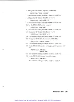
Page 156: ...resent OUTPUT Vxi I FUNC DC 3 Set the HP E1440A DC offset to 5 V and calibrate OUTPUT Vxi I VOLT OFFS 5 CAL I 4 The voltmeter reading should be between 4 950 and 5 050 V 5 Change the HP E1440A DC offset to 5 V OUTPUT Vxi VOLT OFFS 5 6 The voltmeter reading should be between 4 950 and 5 050 V Attenuator Test This procedure continues from the previous one 7 Set the DC offset to the positive and nega...

Page 157: ...s procedure continues from the previous one 8 Remove the 500 feedthru termination and connect the HP E1440A output directly to the voltmeter input 9 Select the high voltage output on the HP E1440A OUTPUT Vxi OUTP AMPL ON 10 Set the HP E1440A DC offset to 20 V OUTPUT Vxi VOLT OFFS 20 11 The voltmeter reading should be 19 775 to 20 225 V 12 Switch off the high voltage output OUTPUT Vxi I t OUTP AWL ...

Page 158: ... d t h r u c r m l n a i o r 1 Figure C 12 DC Offset Test Set Up 2 Set the HP E1440A output as follows and calibrate High Voltage Output Off Function Sine Frequency 21 MHz Amplitude 1 VP P DC Offset t4 5 V OUTPUT Vxi OUTP AMPL OFF FUNC S1N FREQ 2 1E7 VOLT AMPL 1 VOLT OFFS 4 5 CAL I 3 After amplitude calibration approximately 2 seconds the voltmeter reading should be 4 350 to 4 650 Vdc 4 Change the...

Page 159: ... 5 V OUTPUT Vxi I VOLT OFFS 4 5 13 The voltmeter reading should be 4 440 to 4 560 Vdc 14 Change the HP E1440A frequency to 9 9999 MHz OUTPUT Vxi I FREQ 9 9999E6 15 The voltmeter reading should be 4 350 to 4 650 Vdc 16 Set the HP E1440A function to triangle and frequency to 9 9 kHz OUTPUT Vxi FUNC TRI FREQ 9 9E3 17 The voltmeter reading should be 4 440 to 4 560 Vdc 18 Set the HP E1440A function to ...

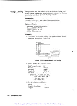
Page 160: ...pter Procedure 1 Connect the HP E1440A and the high speed voltmeter through the divider as shown in Figure C 13 Hlgh Speed DVM HP E1400B 0 2 5 H 1 iZ0 Figure C 13 Triangle Linearity Test Set Up 2 Set the HP E1440A output as follows High Voltage Output Off Function Triangle Frequency 10 kHz Amplitude 10 VP P DC Offset 0 V OUTPUT Vxi OUTP AMPL OFF FUNC TR1 FREq 1E4 VOLT AMPL 10 VOLT OFFS 0 3 Set the...

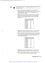
Page 161: ...braically add the voltages recorded in the Positive Slope Measurement column and enter the total in the C y space 7 Measure the voltage at each 10 segment point on the negative slope by setting the voltmeter delay to the following Enter on the Performance Test Record in the appropriate spaces under Negative Slope Measurement Delay 0 00008 0 000085 0 00009 0 000095 0 0001 0 000105 0 00011 0 000115 ...

Page 162: ...lated 13 Determine the value of Q using the equation 14 Calculate the best fit straight line y7value for each point yl through y9 using the equation Enter each result on the Performance Test Record in the Best Fit Straight Line column 15 For each delay x subtract the calculated voltage y from the measured voltage y Find the largest positive voltage difference VmX and the largest negative differenc...

Page 163: ...erator Serial No Report No Date Test Facility Test Conditions Installed Options Ambient Temperature C Relative Humidity Line Frequency Hz Special Notes Page 1 of 10 Performance tests C 39 Artisan Technology Group Quality Instrumentation Guaranteed 888 88 SOURCE www artisantg com ...

Page 164: ...e Counter Digital Voltmeter Spectrum Analyzer AC Voltmeter Frequency Synthesizer High speed DC Voltmeter Power Meter Power Sensor Controller Command Module VXI Mainframe Model No Serial No Trace No Cal Due Date C 40 Performance tests Page 2 of 10 Artisan Technology Group Quality Instrumentation Guaranteed 888 88 SOURCE www artisantg com ...

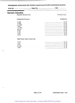
Page 165: ...ion Test Fundamental Frequency 20 MHz 15 MHz 14 9 MHz 2 MHz 1 99 MHz 200 kHz 50 kHz 10 kHz 1 kHz 100 Hz High Voltage Output Option 001 100 Hz 1 kHz 10 kHz 200 kHz 1 MHz Page 3 of 10 Pass 0Fail 0 Specification Performance tests C 41 Artisan Technology Group Quality Instrumentation Guaranteed 888 88 SOURCE www artisantg com ...

Page 166: ... MHz 6 100 MHz 8 100 MHz 10 100 MHz 12 100 MHz 14 100 MHz 16 100 MHz 18 100 MHz 20 100 MHz 5 001 MHz 5 0001 MHz 5 00001 MHz 5 000001 MHz 20 001 MHz 20 001 MHz 20 001 MHz 20 001 MHz C 42 Performance tests 2 l spur 3 2 spur Page 4 of 10 Pass 0Fail 0 Specification Artisan Technology Group Quality Instrumentation Guaranteed 888 88 SOURCE www artisantg com ...

Page 167: ... MHz Square 10 MHz Triangle 10 kHz 100 000 ns Ramp 10 kHz 100 000 ns Pass 0Fail 0 Phase Increment Accuracy Phase Increment Accuracy Test Pass 0Fail 0 Measured Minimum Time Maximum Difference Zero Phase Time Reference loIncrement Time Interval 13 89 ns 41 67 ns 10 Increment Time Interval 263 89 ns 291 67 ns 100 Increment Time 2763 89ns 2791 67ns Interval Page 5 of 10 Performance tests C 43 Artisan ...

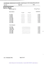
Page 168: ...amp 500 Hz Square 101 kHz Triangle 10 kHz Pos Ramp 10 kHz Neg Ramp 10 kHz Amplitude 3 V p p Square 99 9 Hz Triangle 99 9 Hz Pos Ramp 99 9 Hz Neg Ramp 99 9 Hz Square 1kHz Triangle 2 kHz Pos Ramp 500 Hz Neg Ramp 500 Hz Square 101kHz Triangle 10 kHz Pos Ramp 10 kHz Neg Ramp 10 kHz Minimum 3 455 v 3 455 v 3 455 v 1 037 V 1 037 V 1 037 V 0 3370 V 0 3370 V 0 3370 V Minimum 9 95 v 9 85 V 9 85 V 9 85 V 9 ...

Page 169: ...e 10 V p p High Voltage Output Option 001 Sine 40 V p p Minimum 0 978 V 0 973 V 0 973 V 0 973 V 0 978 V 0 973 V 0 973 V 0 973 V 0 900 V 0 938 V 0 888 V 0 888 V Minimum 13 86 V Minimum 1 96 V 1 96 V 1 96 V 1 96 V Minimum 19 14 dBm 19 14 dBm 19 14 dBm 19 14 dBm 19 14 dBm 9 4 dBm 9 4 dBm 9 4 dBm 9 4 dBm 9 4 dBm Pass 0 Pass 0 Page 7 of 10 Measured Measured Measured MEASURED Maximum 1 022 V 1 027 V 1 0...

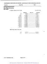
Page 170: ...40A Function Sweep Generator DC Offset Accuracy DC only DC O et Accuracy Test DC Only Pass 0Fail 0 High Voltage Output Option 001 C 46 Performance tests Page 8 of 10 Artisan Technology Group Quality Instrumentation Guaranteed 888 88 SOURCE www artisantg com ...

Page 171: ...5 v Square 999 9 kHz 4 5 v 4 5 v Square 9 9999 MHz 4 5 v Triangle 9 9 kHz 4 5 v Ramp 9 9 kHz 4 5 v Minimum 4 350 V 4 350 V 4 440 V 4 440 V 4 440 V 4 440 V 4 350 V 4 440 V 4 380 V Page 9 of 10 Measured Pass 0Fail 0 Maximum f4 650 V 4 650 V t 4 560 V 4 560 V 4 560 V 4 560 V 4 650 V 4 560 V 4 620 V Performance tests C 47 Artisan Technology Group Quality Instrumentation Guaranteed 888 88 SOURCE www ar...

Page 172: ...rement 3 x times y x Values Linearity Positive Slope Triangle Linearity Test Negative Slope Pass 0Fail 0 x Values Negative Slope Measurement Y x times y Calculated Best fit Straight Line Y Difference Y Y Linearity Negative Slope C 48 Performance tests Artisan Technology Group Quality Instrumentation Guaranteed 888 88 SOURCE www artisantg com ...

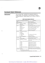
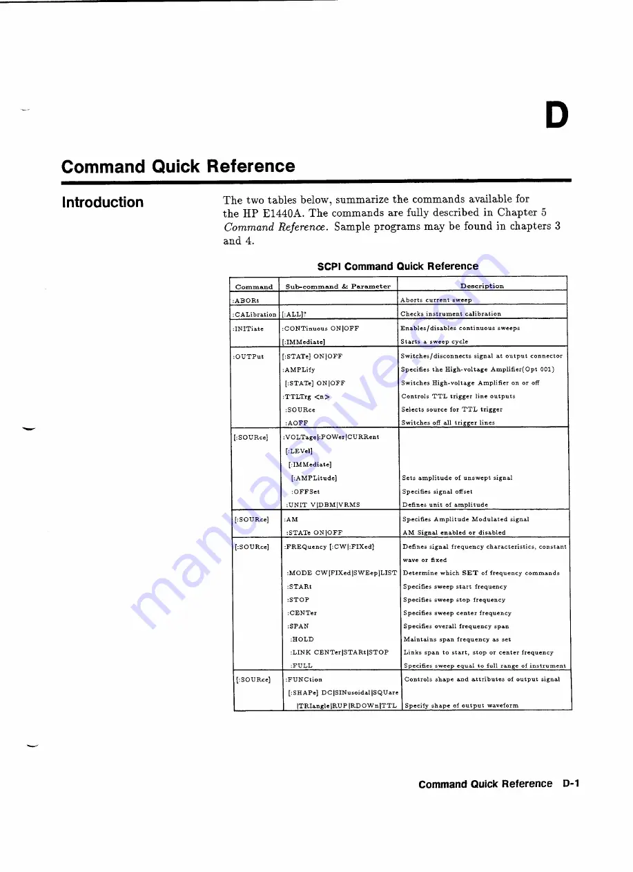
Page 173: ...MMediate AMPLitude OFFSet UNIT VlDBMlVRMS AM Switches off all trigger lines Sets amplitude of unswept signal Specifies signal offset Defines unit of amplitude Specifies Amplitude Modulated signal STAT ONlOFF FREQuency CWI FIXed I I STOP ISpecifies sweep stop frequency I AM Signal enabled or disabled Defines signal frequency characteristics constant MODE CWlFIXedlSWEeplLIST STARt Specifies sweep ce...

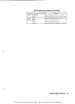
Page 174: ...e occurances for lists POINts Returns no of entries in dwell list SEQuence Defines a sequence for stepping through a list POINts Returns no of entries in sequence list Sets marker on or off ADJust Controls phase offset value relative to reference STEP Controls step size in radians can specify DEG or RAD REFerence TIME Sets duration of sweep RETRace Sets duration of sweep retrace time AUTO ONlOFFlO...

Page 175: ...uency register Loads status register with preset pattern Returns error number to controller Presets instrument to known state Returns SCPI version compatible with instrument Command STATUS STAlhs SYSTem Sub command Parameter QUEStionable FREQ PREset ERROR PREset VERSion Artisan Technology Group Quality Instrumentation Guaranteed 888 88 SOURCE www artisantg com ...

Page 176: ...longer running then sets completed bit in event register Operation Complete Query Recall instrument setting n Reset resets instrument to known state Save instrument setting n Service Request Enable presets bits in SRE register Service Request Enable Query returns content of SRE register Read Status Byte Query returns value of status register content Self Test Query co mands instrument to self test...

Page 177: ...nt frequency cannot be interrogated while FREQ MODE is LIST or SWEEP 108 Parameter not allowed Parameter list is too long 50 parameters Triggered by LIST FREQ xxxx commands or L1ST DWELl command Attempt to program one of the lists mentioned below with more than 50 parameters 108 Parameter not allowed Sequence is too long to be stored Triggered by LIST SEQ command Attempt to program a sequence that...

Page 178: ... Triggered by FUNC command The instrument maintains the output voltage over function changes in the current default unit If the current default unit is not V VRMS or dBm a value legal for one output function may not be legal for another In other words the Vpp voltage that represents X dBm in SIN function is different from the Vpp voltage for X dBm in SQU function 221 Settings confiict Active marke...

Page 179: ...n and dwell must have the same length or must have the length 1 A list with length 1is treated as a list of the required length with the entry in slot 1 duplicated as often as necessary 221 Settings conflict No dBm allowed when post amplifier is active Triggered by VOLT or 0UTP AMPL command It is not permissible to program a dBm voltage while the post amplifier is active and vice versa and it is n...

Page 180: ...R command Cannot accept sync trigger and marker trigger on the same line 221 Settings codict Time distance start mark stop too low 1 5 ms I Triggered by FREQ MODE command The minimal distance between start marker marker marker or marker stop is 1 5 ms 222 Data out of range AC Voltage is out of range Triggered by VOLT command Requested AC voltage is out of absolute bounds 222 Data out of range AC V...

Page 181: ...ed by SAV or RCL command Command argument register number is outside the range 0 9 222 Data out of range Start frequency in list is too high or negative Triggered by FREQ MODE command One of the sequenced start frequencies in the list is too high or negative 222 Data out of range Start frequency is too low Triggered by FREQ MODE command FREQ STAR value is too low negative 222 Data out of range Sta...

Page 182: ...on failed Triggered by FUNC or CAL command This is a hardware fault I Please report error and returned value from CAL command to service personnel 241 Hardware missing Opt 001 post ampaer not installed Triggered by 0UTP AMPL command post amplifier option 001 is missing Hardware not installed 330 Self test failed Device bus read failed Triggered by tst command This is a hardware fault Please report...

Page 183: ...st failed Sweep timer interrupt missing Triggered by TST command The 1ms timer interrupt derived from frac n reference clock is not detectable This is a hardware fault Please report error and returned value from TST command to service personnel 330 Self test failed Sweep timer period time too high Triggered by TST command The period of the 1ms sweep timer is significantly greater than 1ms This is ...

Page 184: ... from TST command to service personnel 330 Self test failed Voltage calibration failed level FLIP FLOP is defect Triggered by TST command This is a hardware fault Please I report error and returned value from TST command to service personnel 330 Self test failed Voltage calibration failed level never above low signal peak Triggered by TST command This is a hardware fault Please report error and re...

Page 185: ... value from TST command to service personnel 330 Self test failed Voltage calibration failed offset or gain out of range Triggered by TST command This is a hardware fault Please report error and returned value from TST command to service personnel Error Messages E 9 Artisan Technology Group Quality Instrumentation Guaranteed 888 88 SOURCE www artisantg com ...

Page 186: ...Ontario L4V 1M8 Canada Telephone 416 678 9430 Telex 069 8644 Fax 416 678 9421 Eastern Europe Hewlett Packard Ges m b H Lieblgasse 1 P O Box 72 A 1222 Vienna Austria Telephone 222 2500 0 Telex 13 4425 HEPA A Northern Europe Hewlett Packard S A V D Hooplaan 241 P O Box 999 NL 118 LN 15 Amstelveen The Netherlands Telephone 20 547 9999 Telex 189 19 hpner South East Europe Hewlett Packard S A World Tra...

Page 187: ... G l l 3LL Telephone 0344 773 100 Telex 848805 Fax 441344 763526 Unitesf States of Customer Information Center America 800 752 0900 6 00AM to 5PM Pacific Time Eastern USA Hewlett Packard Co 4 Choke Cherry Road Rockville MD 20850 Telephone 301 670 4300 Midwestern USA Hewlett Packard Co 5201 Tollview Drive Rolling Meadows IL 60008 Telephone 312 255 9800 Southern USA Hewlett Packard Co 2015 South Par...

Page 188: ...Telephone 415 857 5027 Telex 034 8300 Cable HEWPACK Hewlett Packard Trading S A Bureau de LiaisonJBureau de Support Ville des Lions 9 Hai Galloul DZ BORDJ EL BAHRI Telephone 76 02 07 Fax 281 0387 Sales and Service Offices F 3 Artisan Technology Group Quality Instrumentation Guaranteed 888 88 SOURCE www artisantg com ...

Page 189: ... 19 SOURce LIST 5 20 SOURce MARKer 5 22 SOURce OUTPut 3 2 SOURce PHASe 5 23 SOURce PM 5 24 SOURce ROSCillator 5 25 SOURce SWEep 5 26 STATUS 5 27 SYSTem 5 30 Value coupling 4 9 Connectors amplitude modulation input 1 7 external frequency reference input 1 7 frequency reference output 1 7 marker 1 6 output 1 7 Pen lift 1 7 phase modulation input 1 7 synchronized output 1 7 X drive 1 7 Coupling funct...

Page 190: ...rface VXIbus 4 2 interrupt priority setting 2 4 Key features 1 1 L Logical address 1 2 2 3 mainframe commander 3 3 Marker connector 1 6 Marker distances 416 Microprocessor 4 2 N Node command 5 3 current base 5 4 end 5 4 implied root 5 4 optional 5 3 0 Offset 4 7 OPC 5 37 OPC 5 38 Operation Complete Command 5 37 Operation Complete Query 5 38 Other publications 1 3 output connector 1 7 Output On ind...

Page 191: ...dard Event Status Enable Query 5 34 Standard Event Status Register Query 5 35 Status Byte Register Query 5 45 Status registers B 1 Status reporting B 1 STB 5 43 5 45 STB 5 45 Sweep 413 414 stopping with ABORt 5 8 sweep generator using E1440A as 1 1 Sweep Generator 4 3 Switching on the High voltage option 5 13 Synchronized output connector 1 7 Synthesizer 4 2 Test Equipment C 2 Tests C 10 TST 5 46 ...

Page 192: ...l service in house repair center WE BUY USED EQUIPMENT Sell your excess underutilized and idle used equipment We also offer credit for buy backs and trade ins www artisantg com WeBuyEquipment REMOTE INSPECTION Remotely inspect equipment before purchasing with our interactive website at www instraview com LOOKING FOR MORE INFORMATION Visit us on the web at www artisantg com for more information on ...

Reviews: