
Technical Reference Guide
www.hp.com
7-1
7
Power and Signal Distribution
7.1 Introduction
This chapter describes the power supplies and discusses the methods of general power and signal
distribution. Topics covered in this chapter include:
■
Power distribution (7.2)
■
Power Control (7.3)
■
Signal distribution (7.4)
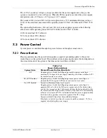
7.2 Power
Distribution
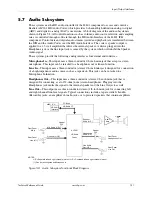
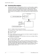
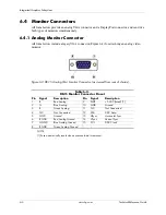
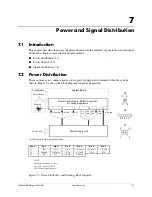
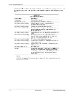
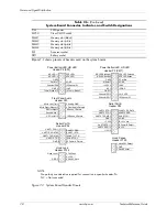
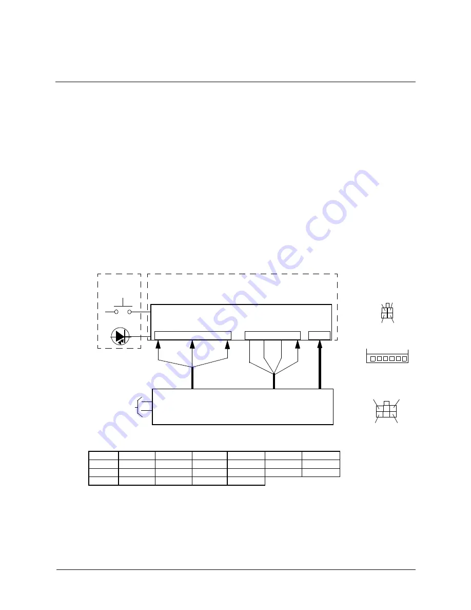
These systems use a common power source power supply unit contained within the system
chassis. Figure 7-1 shows the block diagram for power generation.
NOTES:
Connectors not shown to scale.
All + and
–
values are VDC.
RTN = Return (signal ground)
Figure 7-1. Power Distribution and Cabling, Block Diagram
Conn
Pin 1
Pin 2
Pin 3
Pin 4
Pin 5
Pin 6
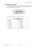
P1
RTN
RTN
–
12 V
+12 Vmain
+12 Vmain
+12 Vsb
P2
FANcmd
Fan Speed
PS On
Pwr Good
RTN
RTN
P3
RTN
RTN
+12 Vcpu
+12 Vcpu
System Board
Power On
Power Control Logic, DC/DC Converter
Front Bezel
& Voltage Regulators
Fan
PS
+12 Vcpu
Power Button
Spd
+12 Vmain
+12 Vsb
90 - 264 VAC
NOTE: Return (RTN or ground) not shown.
-12 V
P1
On
Pwr
Good
P2
P3
P3
1
2
3
4
1
2
3
4
P2
5
6
P1
6
1
3
4
Fan
Cmd
Power Supply Unit
Summary of Contents for 8100 - Elite Convertible Minitower PC
Page 16: ...1 10 www hp com Technical Reference Guide Introduction ...
Page 28: ...2 12 www hp com Technical Reference Guide System Overview ...
Page 74: ...6 8 www hp com Technical Reference Guide Integrated Graphics Subsystem ...
Page 110: ...A 20 www hp com Technical Reference Guide Error Messages and Codes ...


