
7-8
www.hp.com
Technical Reference Guide
Power and Signal Distribution
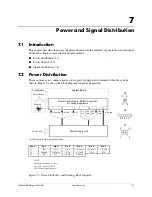
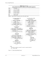
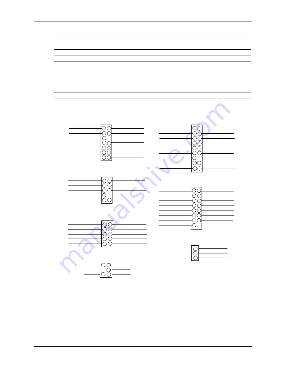
Figure 7-2 shows pinouts of headers used on the sytem boards.
NOTE:
No polarity consideration required for connection to speaker header P6.
NC = Not connected
Figure 7-2. System Board Header Pinouts
P161
SATA power
SW50
Clear CMOS switch
XMM1
Memory slot (black)
XMM2
Memory slot (white)
XMM3
Memory slot (white)
XMM4
Memory slot (white)
XU1
Processor socket
XBT1
Battery socket
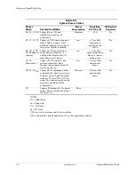
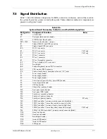
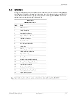
Table 7-6.
(Continued)
System Board Connector, Indicator, and Switch Designations
UART1 RX DATA 3
UART1 TX DATA 5
UART1 DTR 7
GND 9
4 UART1 RTS-
8 UART1 RI-
6 UART1 CTS-
10 Comm A Detect-
Serial Port A
Header P54
UART1 DCD- 1
2 UART1 DSR-
UART2 DTR- 1
UART2 CTS- 3
UART2 TX DATA 5
GND 7
+5.0V 9
2 UART2 RX DATA
4 UART2 DSR-
8 GND
6 UART2 RI-
10 +3.3V aux
UART2 RTS- 11
UART2 DCD- 13
12 Comm B Detect
+12V 15
14 -12V
Serial Port B
Header P52
Hood Lock 1
GND 5
2 Coil Conn
4 +12V
6 Hood Unlock
Hood Lock
Header P124
1 Hood SW Detect
2 GND
3 Hood Sensor
Hood Sense
Header P125
HD LED + 1
HD LED - 3
GND5
2 PS LED +
4 PS LED -
8 GND
Pwr Btn 7
GND 11
Therm Diode A 13
12 NC
Chassis ID0 9
14 Therm Diode C
Power Button/LED, HD LED
Header P5 (SFF)
10 Chassis ID1
HD LED Cathode 1
HD LED Anode 3
GND5
M Reset 7
+5 VDC 9
2 PS LED Cathode
4 PS LED Anode
8 GND
6 Pwr Btn
10 NC
NC 11
GND 13
12 GND
Chassis ID2 15
16 +5 VDC
Power Button/LED, HD LED
Header P5 (CMT)
18 Chassis ID1
Chassis ID0 17
Mic In Right (Sleeve) 3
HP Out Right 5
Sense Send 7
HP Out Left 9
4 Front Audio Detect#
6 Sense_1 Return
10 Sense_2 Return
Front Panel Audio
Header P23
Mic In Left (Tip) 1
2 Analog GND
Summary of Contents for 8100 - Elite Convertible Minitower PC
Page 16: ...1 10 www hp com Technical Reference Guide Introduction ...
Page 28: ...2 12 www hp com Technical Reference Guide System Overview ...
Page 74: ...6 8 www hp com Technical Reference Guide Integrated Graphics Subsystem ...
Page 110: ...A 20 www hp com Technical Reference Guide Error Messages and Codes ...


