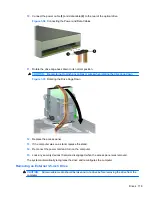
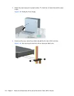
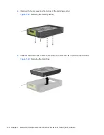
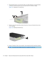
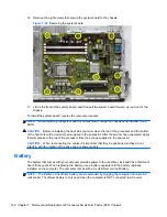
4.
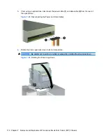
Remove the four screws from the bottom of the hard drive carrier.
Figure 7-47
Removing the Security Screws
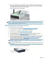
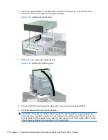
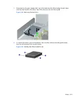
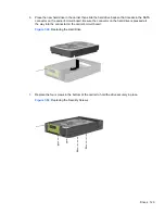
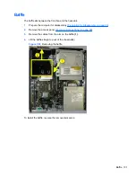
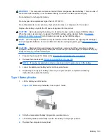
5.
Slide the hard drive back to disconnect it from the carrier then lift it up and out of the carrier.
Figure 7-48
Removing the Hard Drive
128 Chapter 7 Removal and Replacement Procedures Small Form Factor (SFF) Chassis


