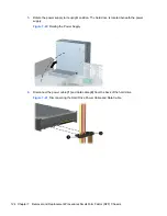
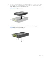
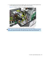
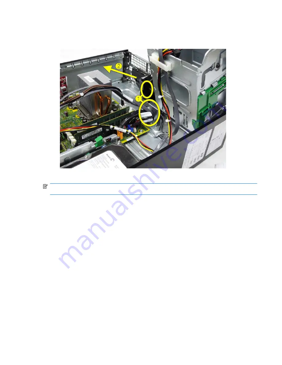
8.
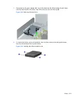
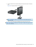
Route the cables through the slots beneath the drive cage
(1)
, pull the assembly (right side first)
into the chassis
(2)
, and then remove the assembly from the computer.
Figure 7-57
Routing the cables and removing the power switch assembly
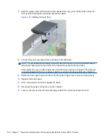
To install the front I/O and power switch assembly, reverse the removal procedure.
NOTE:
Be sure to correctly route the cables beneath the drive cage when reinstalling the assembly.
Proper cable routing prevents damage to the cables and allows the drive cage to close properly.
Front I/O, Power Switch Assembly 135


